14-26 BE1-951 BESTCOMS Software 9328900990 Rev L
Fault Recording
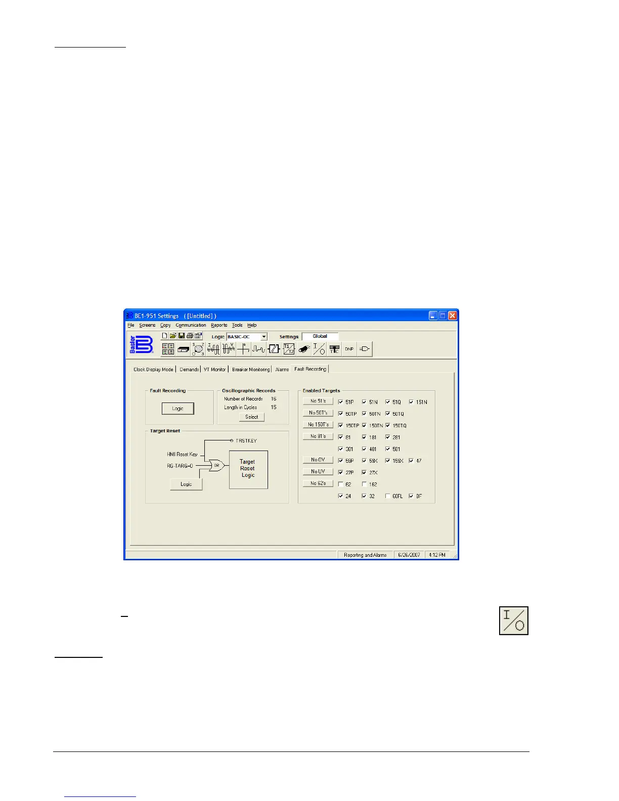
Logic expressions define the three conditions that determine when a fault has occurred. When a fault is
detected by the relay, the relay records (stores in memory) data about the fault. The three conditions that
determine a fault are Trip, Pickup, and Logic Trigger. To define these conditions, click on Fault Recording
- Logic (
Figure 14-35) and then click on Tripped, Pickup, and Logic, in turn, and program the inputs that
define each condition. You may clear existing programming by clicking on the Clear button or clicking on
each individual variable.
The fault recording function can record up to 16 oscillographic records in volatile memory. Because there
is only a specific amount of memory available, as additional faults are recorded, the oldest records are
overwritten. Each record can record only a limited number of data cycles. If you have less than 16
records, you can have more than 15 cycles of data per record. To select the number of cycles of data and
number of records, click on the Oscillographic Records - Select button and click on the number of records
that you want to record.
Logic settings for the Target Reset Logic can be made by clicking on the Target Reset - Logic button and
then clicking on the Reset input. Other logic blocks shown under Target Reset are shown for reference
only. There is no interaction available.
Any protective function, except 62, 162, and 60FL that has a trip will set a target because these functions
have the targets enabled on the Fault Recording tab. If you are using a protective function in a
supervisory capacity and do not want to set a target when the protective function trips, disable that target
by clicking on the specific target. If you want to disable all of the targets for a function such as the
frequency protection function, click on the No 81's button on the left side of the Enabled Targets.
Figure 14-35. Reporting and Alarms Screen, Fault Recording Tab
Inputs and Outputs
Pull down the S
creens menu and select Inputs and Outputs or click on the Inputs and Outputs
icon that is shown at the right margin of this paragraph. This screen has two folder tabs and the
first tab is Inputs 1 - 4.
Inputs 1 -4
There are four programmable inputs in the BE1-951 relay; this tab (
Figure 14-36) allows setting of four
inputs. To program how long the Input 1 contact must be closed to be recognized as closed, first, pull
down the Time Units menu and set the units for the appropriate time measurement. Then, click on the
Input 1, Recognition Time field and enter the new value or use the appropriate (UP or DOWN) arrow
buttons to set the new value. To program how long the Input 1 contact must be open to be recognized as
open, click on the Input 1, Debounce Time and enter the new value or use the appropriate (UP or DOWN)
arrow buttons to set the new value within the range of 4 - 255 ms.