9328900990 Rev L BE1-951 Protection and Control 4-77
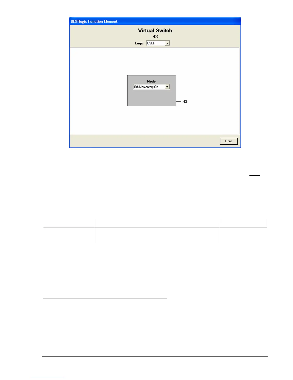
Figure 4-72. BESTlogic Function Element Screen, 43
At the top center of the BESTlogic Function Element screen is a pull-down menu labeled Logic. This
menu allows viewing of the BESTlogic settings for each preprogrammed logic scheme. User must
be
selected on this menu in order to allow changes to the mode and inputs of the element.
Enable the Virtual Switch element by selecting its mode of operation from the Mode pull-down menu.
Select Done when the settings have been completely edited.
Table 4-44 summarizes the BESTlogic settings for Virtual Selector Switches.
Table 4-44. BESTlogic Settings for Virtual Selector Switches
Function Range/Purpose Default
Mode
0 = Disabled
1 = On/Off/Pulse
2 = On/Off
3 = Off/Momentary On
0
Example 1. Make the following settings to the 43 Virtual Switch element.
Figure 4-72 illustrates these
settings.
Logic: User
Mode: Off/Momentary On
Select Before Operate Control of Virtual Selector Switches
The state of each virtual selector switch can be controlled at the human-machine interface (HMI) through
Screens 2.1.1 through 2.1.4. Control is also possible through the ASCII command interface by using the
select-before-operate command’s CS-x43 (control select-virtual switch) and CO-x43 (operate select-
virtual switch). This is not possible through BESTCOMS. A state change takes place immediately without
having to execute an EXIT – SAVE settings command.