4-74 BE1-951 Protection and Control 9328900990 Rev L
V0IN inputs:
Test: 60FL=FALSE & 3P4W=TRUE & (IN > minimum) & (IN > I1*8%) & (V0 > minimum)
V0IG inputs:
Test: 60FL=FALSE & 3P4W=TRUE & (IG > minimum) & (V0 > minimum)
VXIN inputs:
Test: (IG > minimum) & (IN > I1*8%) & (VX > minimum)
VXIG inputs:
Test: (IG > minimum) & (VX > minimum)
I Block and V Block settings are made using the SP-60FL command.
The 60FL element detects fuse loss and loss of potential by using voltage and current thresholds that are
expressed as a percentage of the nominal voltage and current values. See Section 3, Input and Output
Functions, for information on changing the nominal voltage and current values using the SG-NOM
command.
VIRTUAL LOCKOUT PROTECTION
86 - Virtual Lockout Protection
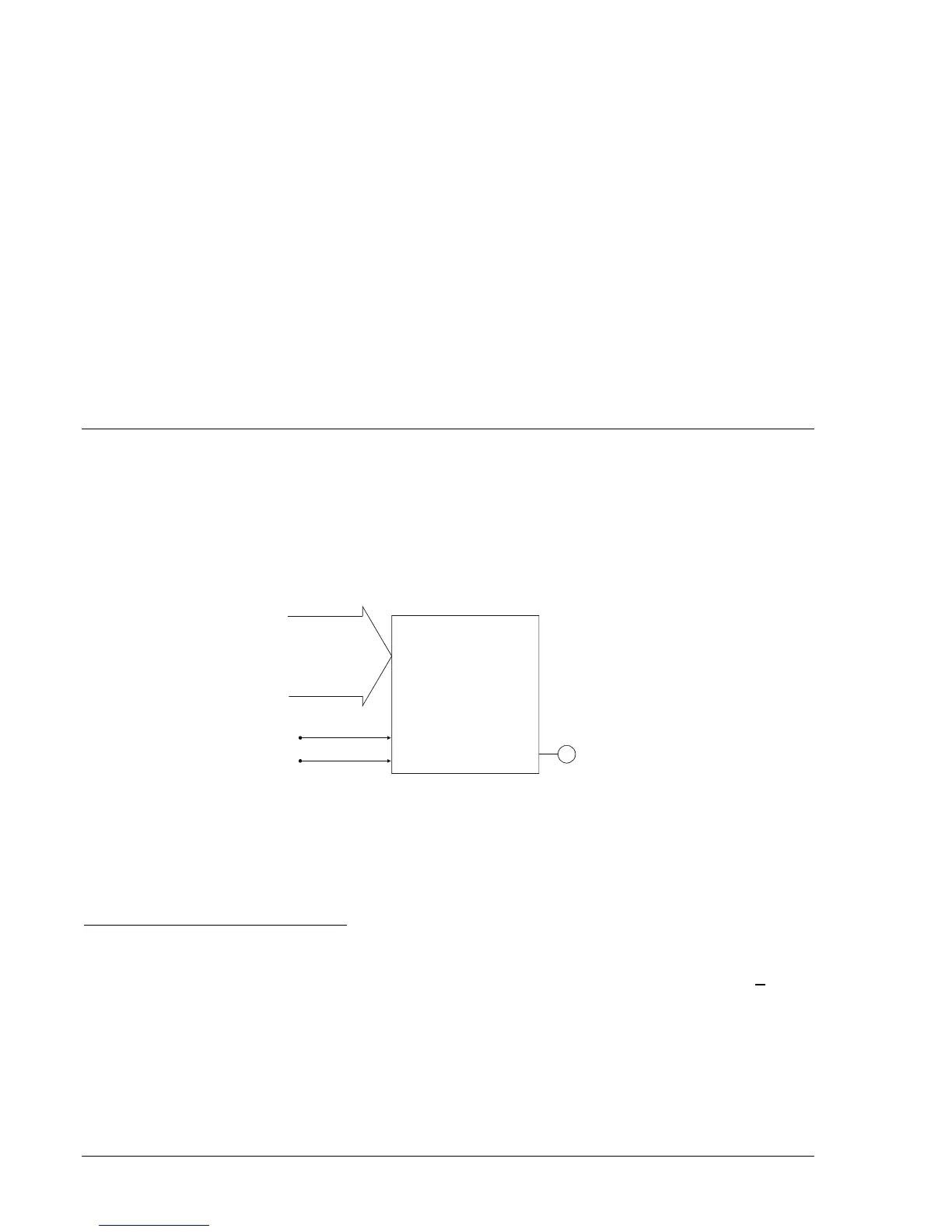
BE1-951 virtual lockout protection consists of two protection elements: 86 and 186. Each element has
three available inputs that are BESTlogic programmable. The element can be enabled or disabled using
the Mode input. In addition to the Mode input, the 86 element also has a Trip input and Reset input. All
three of these inputs are BESTlogic programmable. See
Figure 4-69.
LOCKOUT
(LATCH)
(86)
Mode =
0-disable
1-enable
P0007-04
02-15-01
86
TRIP
RESET
Figure 4-69. Virtual Lockout Logic Block
When the Trip input is asserted the output of the function becomes TRUE. When the Reset input is
asserted the output becomes FALSE. If for some reason both inputs are asserted at the same time, the
Trip input will have priority and drive the functions output TRUE. The state of the function is stored in
nonvolatile memory.
BESTlogic Settings for Virtual Lockout
BESTlogic settings are made from the BESTlogic Function Element screen in BESTCOMS.
Figure 4-70
illustrates the BESTCOMS screen used to select BESTlogic settings for the lockout protection element.
To open the BESTlogic Function Element screen for logic timers, select Logic Functions from the S
creens
pull-down menu and select the 86/186 tab. Then select the BESTlogic button for the element to be
changed. Alternately, settings may be made using SL-86 and SL-186 ASCII command.