8-32 BE1-951 Application 9328900990 Rev L
The components of BUS logic are summarized in Tables 8-17, 8-18, 8-19, and 8-20. Figure 8-10 shows a
one-line drawing for the BUS logic scheme. A diagram of BUS logic is shown in
Figure 8-11.
The components of BACKUP logic are summarized in Tables 8-21, 8-22, 8-23, and 8-24.
Figure 8-12
shows a one-line drawing for the BACKUP logic scheme. A diagram of BACKUP logic is shown in
Figure
8-13.
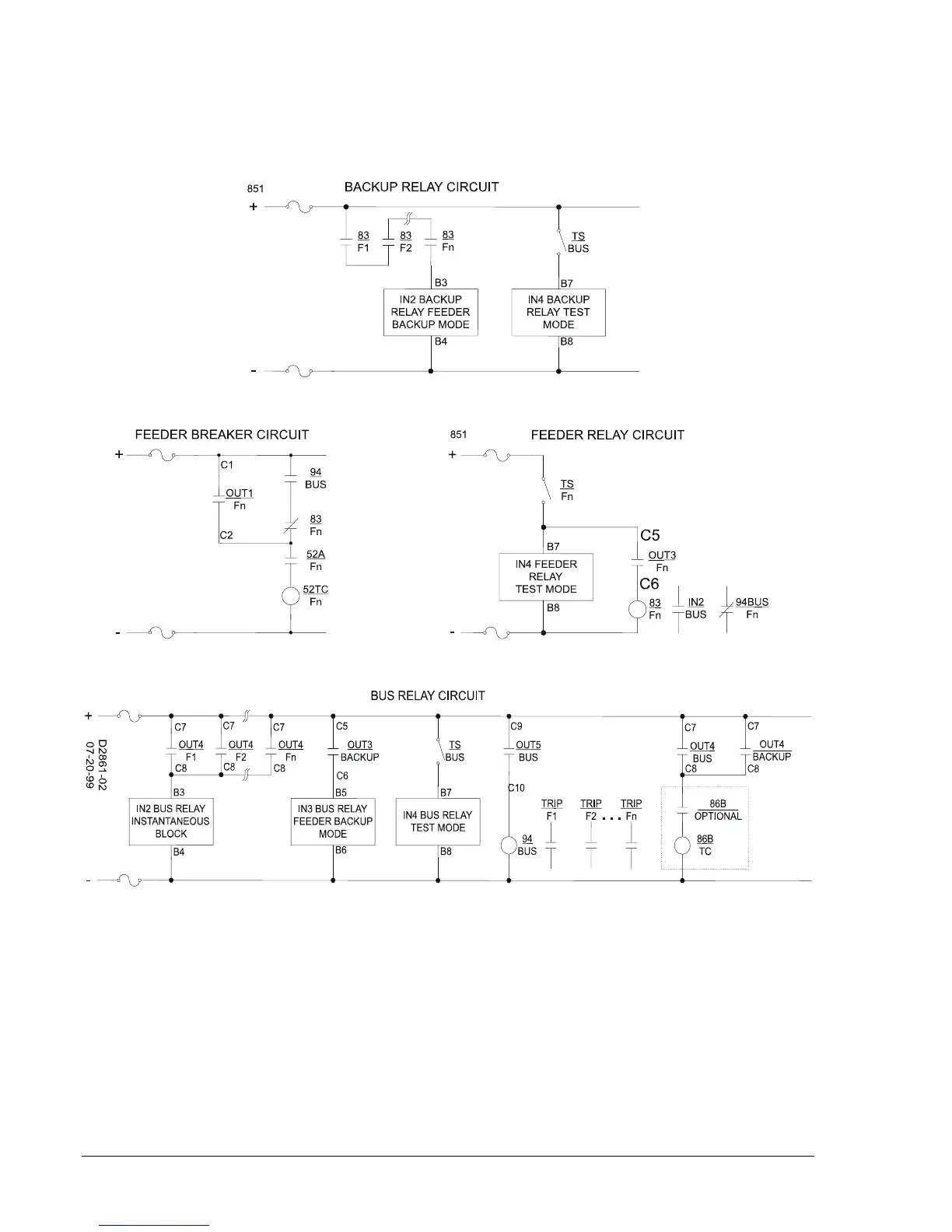
Figure 8-9. Device Interconnection for Integrated Protection System
Normal Operation - Control
The virtual breaker control switch (101) is programmed to provide manual trip and close control of the
breaker. Manual breaker control can be achieved by using the front panel HMI or by entering ASCII
commands through the communication ports. Control functions of this logic scheme use both traditional
contact sensing inputs and virtual switches. Virtual switches that are not needed may simply go unused.
The contact sensing inputs can be freed up for other uses by utilizing the virtual switches for other control
functions.