4-12 BE1-951 Protection and Control 9328900990 Rev L
CS/CO-GROUP Command Examples:
Example 1. Read the current status of setting group override.
>CO-GROUP
L
Example 2. Override logic control and change the active setting group to SG1.
>CS-GROUP=1
GROUP=1 SELECTED
>CO-GROUP=1
GROUP=1 EXECUTED
Example 3. Return control of the active setting group to the automatic setting group logic.
>CS-GROUP=L
GROUP=L SELECTED
>CO-GROUP=L
GROUP=L EXECUTED
Retrieving Setting Group Control Status from the Relay
The active setting group can be determined from HMI Screen 1.5.6 or by using the RG-STAT command.
Section 6, Reporting and Alarm Functions, General Status Reporting, provides more information about
determining the active setting group. The active group cannot be determined using BESTCOMS.
Logic override status can be determined from HMI Screen 2.3.1 or through the RG-STAT command.
Section 6, Reporting and Alarm Functions, General Status Reporting, provides more information about
determining logic override status. Logic override cannot be determined using BESTCOMS.
OVERCURRENT PROTECTION
The BE1-951 includes instantaneous elements for Phase, Neutral, and Negative-Sequence, as well as
time overcurrent elements for phase, neutral or ground, and negative-sequence.
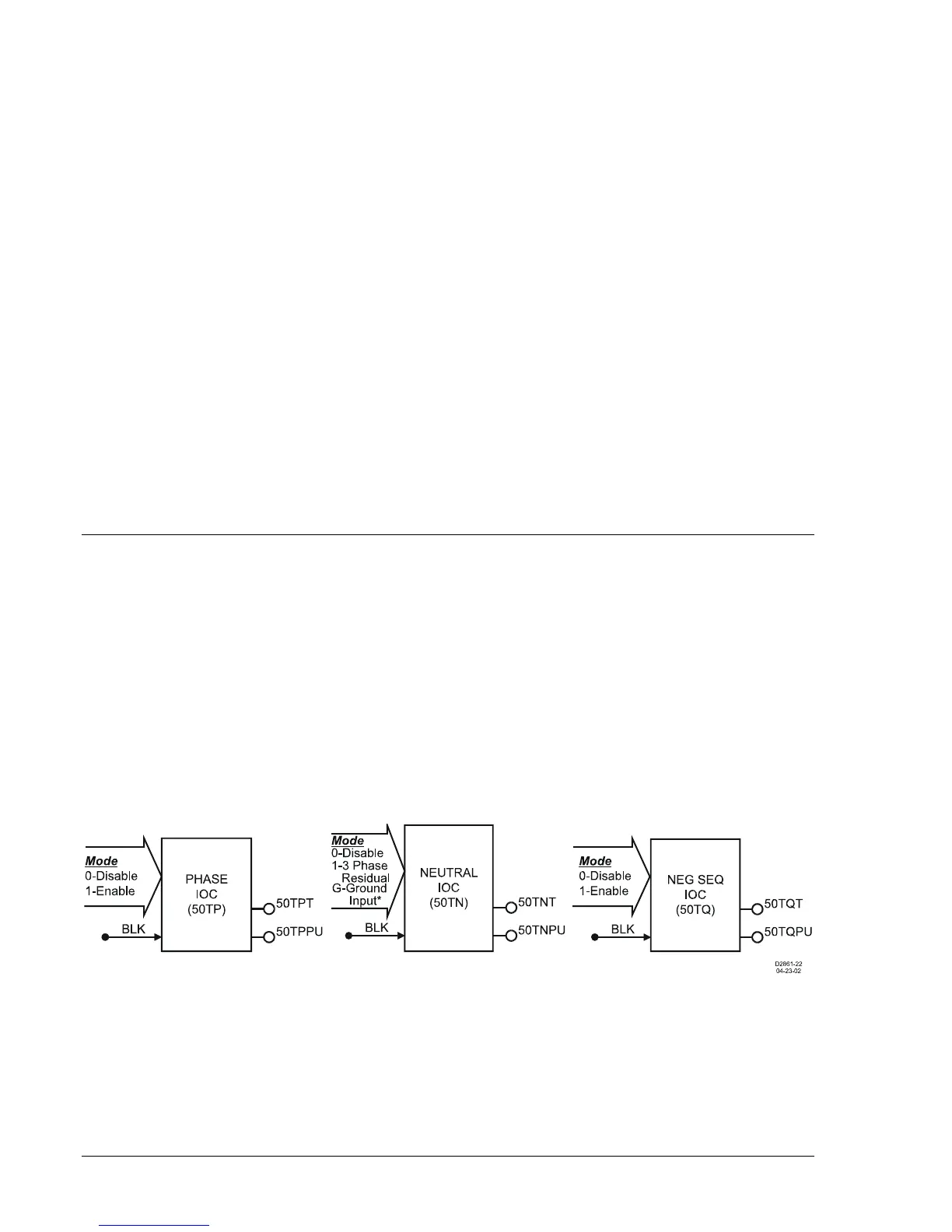
50T - Instantaneous Overcurrent Protection with Settable Time Delay
There are two BESTlogic elements for phase (50TP and 150TP), two elements for ground (50TN and
150TN), and two elements for negative-sequence (50TQ and 150TQ) instantaneous overcurrent
protection. The alphanumeric designation for each element contains the letter T to indicate that the
element has an adjustable time delay. If an element has a time delay setting of zero, then that element
will operate as an instantaneous overcurrent relay. Each element can also be set as either directional or
nondirectional. Refer to the paragraph, 67 Directional Overcurrent, for more information.
The 50TP, 50TN, and 50TQ instantaneous overcurrent elements are shown in
Figure 4-11. The 150TP,
150TN, and 150TQ elements are identical to their counterparts. Each element has two logic outputs:
Pickup (PU) and Trip (T).
Figure 4-11. Instantaneous Overcurrent Logic Blocks
Each element has a Block (BLK) input that can be used to disable the function. A BESTlogic expression
is used to define the BLK input. When this expression is TRUE, the element is disabled by forcing the
outputs to logic zero and resetting the timers to zero. This feature functions in a similar way to a torque
control contact of an electro mechanical relay.
A Logic Mode input allows each instantaneous overcurrent element to be enabled or disabled. The
ground elements, 50TN and 150TN, have additional mode selections. Element operation can be based
on calculated three-phase 3I0 current values (Mode 1) or on measured ground current through the