4-36 BE1-951 Protection and Control 9328900990 Rev L
27P/59P - Phase Undervoltage/Overvoltage Protection
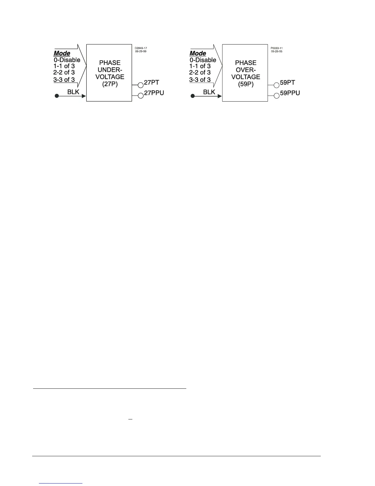
Figure 4-29 illustrates the inputs and outputs of the Phase Undervoltage/Overvoltage Logic Blocks.
Figure 4-29. Phase Undervoltage/Overvoltage Logic Blocks
Each element has two logic outputs: pickup and trip. When the monitored voltage decreases below the
undervoltage pickup setting (27P) or increases above the overvoltage pickup setting (59P), the pickup
output becomes TRUE and the element starts timing toward a trip. The trip output becomes TRUE when
the element timer times out.
The Block (BLK) input is used to disable protection. A BESTlogic expression defines how the BLK input
functions. When this expression is TRUE, the element is disabled by forcing the outputs to logic 0 and
resetting the timer. This feature functions in a similar way to the torque control contact of an
electromechanical relay.
An element is enabled or disabled by the Mode input. Any one of four modes is possible for the phase
undervoltage and phase overvoltage elements. Selecting Mode 0 disables protection. Mode 1 activates
protection when one of the three phases of voltage decreases below the pickup setting (27P) or increases
above the pickup setting (59P). Mode 2 requires two of the three phases of voltage to be beyond the
pickup setting. Mode 3 requires all three phases of voltage to be beyond the pickup setting. More
information about logic mode selections is provided in the BESTlogic Settings for Phase
Undervoltage/Overvoltage in this section.
The phase undervoltage and overvoltage protective functions each include a timer and three independent
comparators, one for each phase. If the voltage decreases below (27P) or increases above (59P) the
pickup setting (on the number of phases defined by the Mode setting), the pickup output asserts. When
the time delay expires, the trip logic output asserts. The 27P/59P functions can be set to monitor VPP or
VPN. This is determined by the 27/59 Mode parameter of the phase VT connections setting. For more
information on the SG-VTP setting for PP or PN voltage response, see Section 3, Input and Output
Functions, Power System Inputs.
The pickup setting determines the voltage pickup level of the element. The time delay setting controls
how long it takes for the trip output to become TRUE after the pickup output becomes TRUE. When the
monitored voltage decreases below (27P) or increases above (59P) the pickup threshold, the pickup
output (PU) becomes TRUE and the timer starts. If the voltage remains in the pickup range for the
duration of the time delay setting, the trip output (T) becomes TRUE. If the voltage increases above the
dropout ratio of 102 percent (27P) or decreases below the dropout ratio of 98 percent (59P), the timer is
reset to zero.
If the 60FL element trip logic is TRUE and V block is enabled for phase blocking (P), all functions that use
the phase voltage are blocked.
If the target is enabled for the element, the target reporting function will record a target for all phases that
are picked up when the protective function trip output is TRUE and the fault recording function trip logic
expression is TRUE. See Section 6, Reporting and Alarm Functions, Fault Reporting, for more
information about target reporting.
BESTlogic Settings for Phase Undervoltage/Overvoltage
BESTlogic settings are made from the BESTlogic Function Element screen in BESTCOMS.
Figure 4-30
illustrates the BESTCOMS screen used to select BESTlogic settings for the Time Undervoltage element.
(The 59P Time Overvoltage is set in a similar manner once the 59P tab is selected.) To open the screen,
select Voltage Protection from the S
creens pull-down menu, and select the 27P tab. Alternately, settings
may be made using the SL-27P (undervoltage) and SL-59P (overvoltage) ASCII commands.