4-20 BE1-951 Protection and Control 9328900990 Rev L
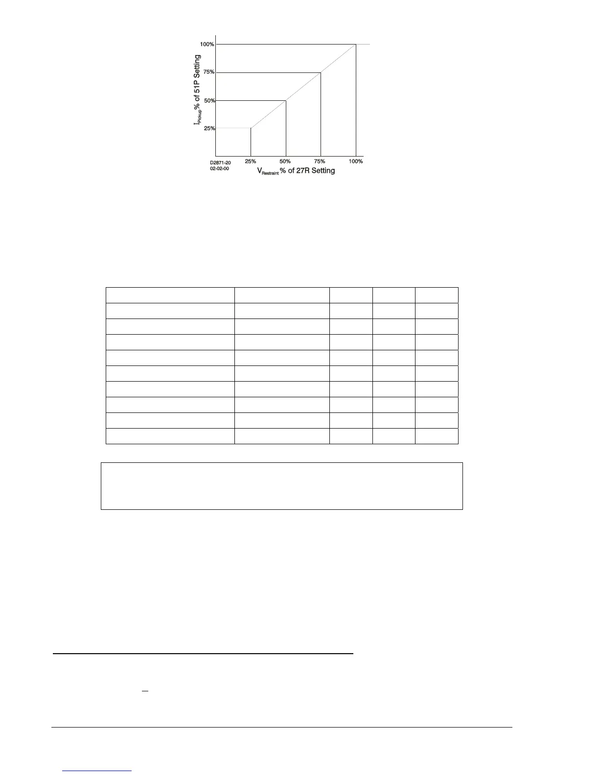
Figure 4-17. 51P Pickup Level Compensation
The 51/27R function can be set to monitor either Vpp or Vpn depending upon the VTP connection
settings. See Section 3, Input and Output Functions, Power System Inputs, for more detail on how to set
the VTP Connections.
Table 4-8 shows which voltage measurements are used by each phase
overcurrent element for each possible VTP connection and 51/27 voltage monitoring mode setting.
Table 4-8. VTP Connection Cross Reference
VTP Connection 51/27 Mode 51A 51B 51C
4W Vpp Vab Vbc Vca
4W Vpn Van Vbn Vcn
3W Vpp Vab Vbc Vca
AN Vpn Van N/A N/A
BN Vpn N/A Vbn N/A
CN Vpn N/A N/A Vcn
AB Vpp Vab N/A N/A
BC Vpp N/A Vbc N/A
CA Vpp N/A N/A Vca
When single-phase voltage sensing is used, only the overcurrent element on the phase with voltage
magnitude information is affected by the 51/27R feature. Thus, in voltage control mode, the 51 elements
on the two unmonitored phases will always be disabled. In voltage restraint mode, the 51 elements on the
two unmonitored phases will not have their overcurrent pickup settings adjusted from 100%.
The VT fuse loss detection function (60FL) can also be set to supervise the 51/27R function. It is possible
to set the 60FL function to automatically prevent misoperation on loss of sensing voltage. When the
51/27R function is set for control and a 60FL condition is detected, the phase overcurrent elements will be
disabled. When the 51/27R function is set for restraint and a 60FL condition is detected, the phase
overcurrent elements will remain enabled but the pickup will not be adjusted from 100% of its setting. See
the paragraph titled Voltage Transformer Fuse Loss Detection later in this section for more information.
Operating Settings for Voltage Restraint/Control for Time Overcurrent
Operating settings are made using BESTCOMS.
Figure 4-16 illustrates the BESTCOMS screen used to
select operational settings for the Time Overcurrent element. To open the screen, select Overcurrent
Protection from the S
creens pull-down menu and select the 51 tab. Alternately, settings may be made
using S<g>-27R ASCII commands or from the HMI Screen 5.x.7.5 where x equals 1 for Setting Group 0,
2 for Setting Group 1, 3 for Setting Group 2, and 4 for Setting Group 3.
NOTE
For single sensing, the un-monitored phase is not restrained or controlled. These
phases are marked in the table by N/A.