9328900990 Rev L BE1-951 Input and Output Functions 3-3
For AB, BC, or CA VT connection, with ABC phase-sequence:
()
°−Φ×=
Φ
30cos3
3 xxy
IVWATTs
Equation 7
()
°−Φ−×=
Φ
30sin3
3 xxy
IVVARs
Equation 8
xxy
IVandtypengsensionbasedCorBAyandxwhere ∠−∠==
φ
,,:
For AB, BC, or CA VT connection, with ACB phase-sequence:
()
°+Φ×=
Φ
30cos3
3 xxy
IVWATTs
Equation 9
()
°+Φ−×=
Φ
30sin3
3 xxy
IVVARs
Equation 10
xxy
IVandtypengsensionbasedCorBAyandxwhere ∠−∠==
φ
,,:
Measurement Functions Setup
The BE1-951 requires information about the power system and its current and voltage transformers to
provide metering, fault reporting, fault location, and protective relaying. This information is entered using
BESTCOMS. Alternately, it may be entered at the HMI (see Section 10, Human-Machine Interface) or
through the communication port using the following ASCII commands: SG-CT, SG-VTP, SG-VTX, SG-
FREQ, SG-NOM, and SG-PHROT. The SG-LINE command for Power Line Parameters is found Section
6, Reporting and Alarm Functions, Fault Reporting, Distance to Fault.
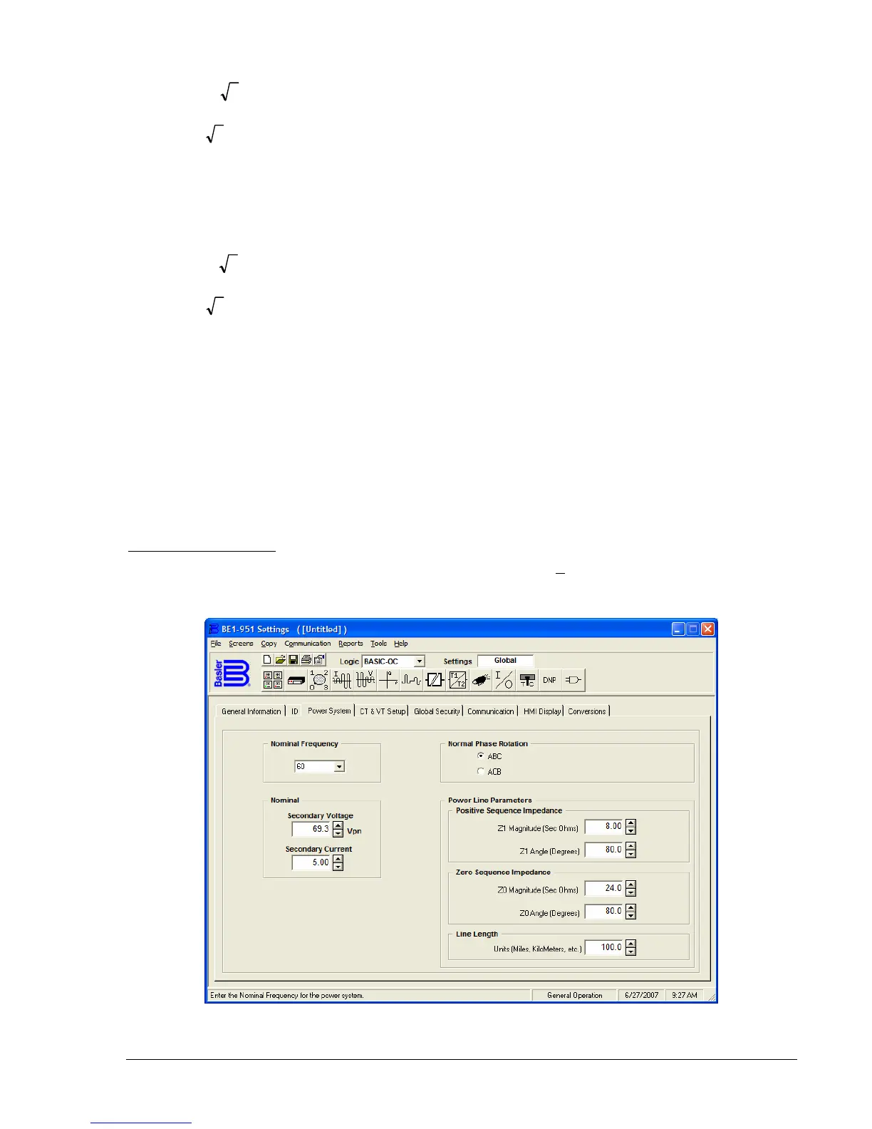
Power System Settings
To enter power system settings, select General Operation from the S
creens pull-down menu. Then select
the Power System tab. Refer to
Figure 3-1.
Figure 3-1. General Operation, Power System Tab