3-4 BE1-951 Input and Output Functions 9328900990 Rev L
Use the pull down buttons and menus to make the power systems settings. Nominal Frequency can be
set for 50 hertz or 60 hertz power systems. Nominal Phase Rotation can be set for either ABC rotation or
ACB rotation.
Nominal Secondary Voltage and Current Settings, V
nom
and I
nom
, are used by the 60FL function,
directional calculations for the 67 elements, and DNP 3.0 analog event reporting functions. V
nom
is also
used in the volts/hertz (24) calculation, and I
nom
is also used in the 46 time curve calculation (K factor) of
the negative-sequence current (51Q) element.
Nominal Voltage (V
nom
) is defined as the secondary phase-neutral voltage for all sensing connections.
That is, even if the user has selected 3-wire, AB, BC, or CA phase-phase sensing connections, V
nom
must
be set for the phase-neutral equivalent. For example, if a 3-wire open delta voltage source with a phase-
phase voltage rating of 120 volts is connected, the nominal voltage must be set at 120/
3 or 69.3 volts.
I
nom
can be either the secondary rating of the CT (1 or 5 amp) or the secondary current allowed by the CT
ratio.
In BESTCOMS for the BE1-951, under General Operation Screen, Power System tab, are settings for
Nominal Voltage and Current. Nominal Voltage (V
nom
) is the nominal voltage rating corresponding to 1 pu
volts and is configured as a phase-neutral secondary value.
Nominal Current (I
nom
) is the nominal phase current rating for the system corresponding to 1 pu current
and is configured in secondary amps. If 1 pu secondary current is unknown, then setting I
nom
to the
secondary CT rating (1 or 5 A) is acceptable for most applications. However, this could degrade the
expectation (not accuracy) of the time curve for the 51Q element as I
nom
is used to directly compute
multiple of pickup (MOP) and time delay.
Power Line Parameters are used for fault location. For more information on Distance to Fault, see Section
6, Reporting and Alarm Functions, Fault Reporting, Distance to Fault.
CT & VT Settings
To enter current and power transformer settings, select General Operations from the S
creens pull-down
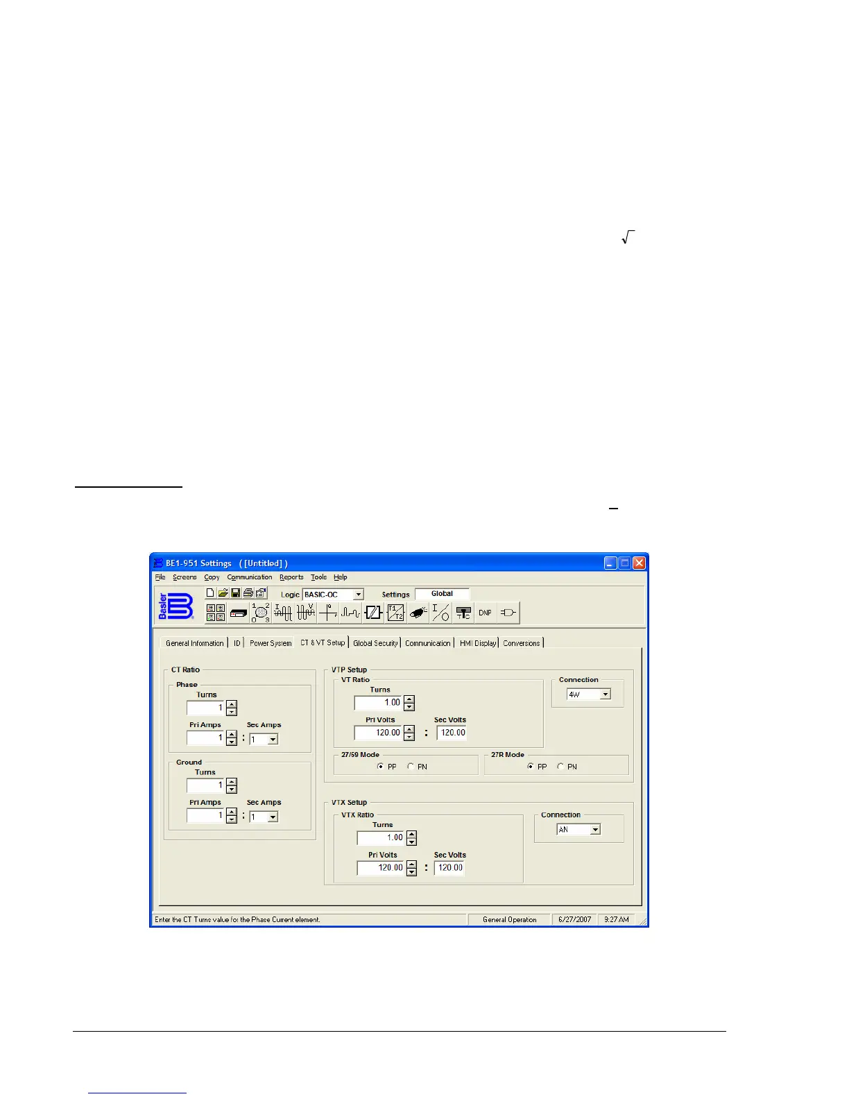
menu. Then select the CT & VT Setup tab. Refer to
Figure 3-2.
Figure 3-2. General Operation Screen, CT & VT Setup
CT Ratio. The BE1-951 requires setting information on the CT ratio. These settings are used by the
metering and fault reporting functions to display measured quantities in primary units. Sec. Amps is used
to select secondary CT amps. Pri Amps will display the primary amps of the CT based on the number of