9328900990 Rev L BE1-951 Protection and Control 4-71
The sync-check output, 25, only provides closing supervision for the live line/live bus condition. The
voltage monitor function 25VM is provided for conditions where the bus and/or the line are dead. A live
condition for either the VP or the VX is determined when the measured voltage on the respective input is
above the LV threshold or is below the DV threshold.
For the phase voltage input, if the connection is three phase, 3W, or 4W, all three phases are tested and
must be above the LV threshold for a live condition to be TRUE. Similarly, all three phases must be below
the DV threshold for a dead condition to be TRUE.
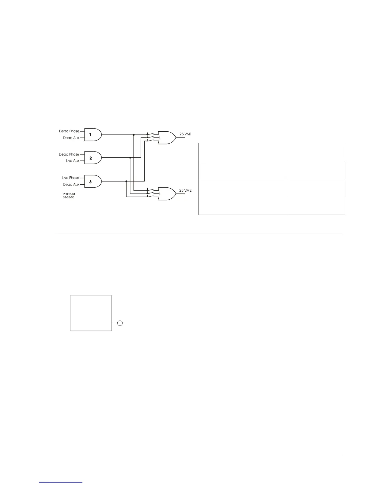
The function includes two independent outputs, 25VM1, and 25VM2 as illustrated in
Figure 4-65. The
logic conditions are summarized in
Table 4-40. Any combination of logic settings can be selected as
shown in
Table 4-40. When a logic condition is selected, it closes the respective switch in Figure 4-65
associated with each of the outputs. The two independent logic outputs might be used to set up different
closing supervision criteria for automatic reclose versus manual close used, for example.
Table 4-40. Voltage Monitor Logic Settings
Voltage Monitor Logic
Condition
Logic Setting
Dead Phase and Dead Aux 1
Dead Phase and Live Aux 2
Figure 4-65. 25VM Logic
Live Phase and Dead Aux 3
VOLTAGE TRANSFORMER FUSE LOSS DETECTION
60FL - Fuse Loss Detection
BE1-951 relays have one 60FL element that can be used to detect fuse loss or loss of potential in a
three-phase system. The 60FL element is illustrated in
Figure 4-66. When the element logic becomes
TRUE, the 60FL logic output becomes TRUE. A logic diagram is shown in
Figure 4-67 and the 60FL logic
parameters are found in
Table 4-41.
D2861-01
07-13-00
VT FUSE
LOSS
(60FL)
60F
Figure 4-66. 60FL Element
Trip Logic: 60FL Trip = (A * B * C * D * G) + (E * F * B * G)
(See
Table 4-33.)
Reset Logic: 60FL Reset = H * /K */L (See
Table 4-33.)