9328900990 Rev L BE1-951 Protection and Control 4-33
()
2
T
1
D
−
=
M
T
T
100**
FST
E
DT
T
RR
=
Equation 4-4. Time to Trip Equation 4-5. Time to Reset
where:
T
T
= Time to trip
T
R
= Time to reset
D
T
= Time dial trip
D
R
= Time dial, reset
E
T
= Elapsed time
M = Multiples of pickup = (measured V/Hz) divided by (V/Hz PU setting)
n = Curve exponent (0.5, 1, 2)
FST = Full scale trip time (T
T
)
E
T
/FST = Fraction of total travel toward trip that integration had progressed to. (After a trip,
this value will be equal to one.)
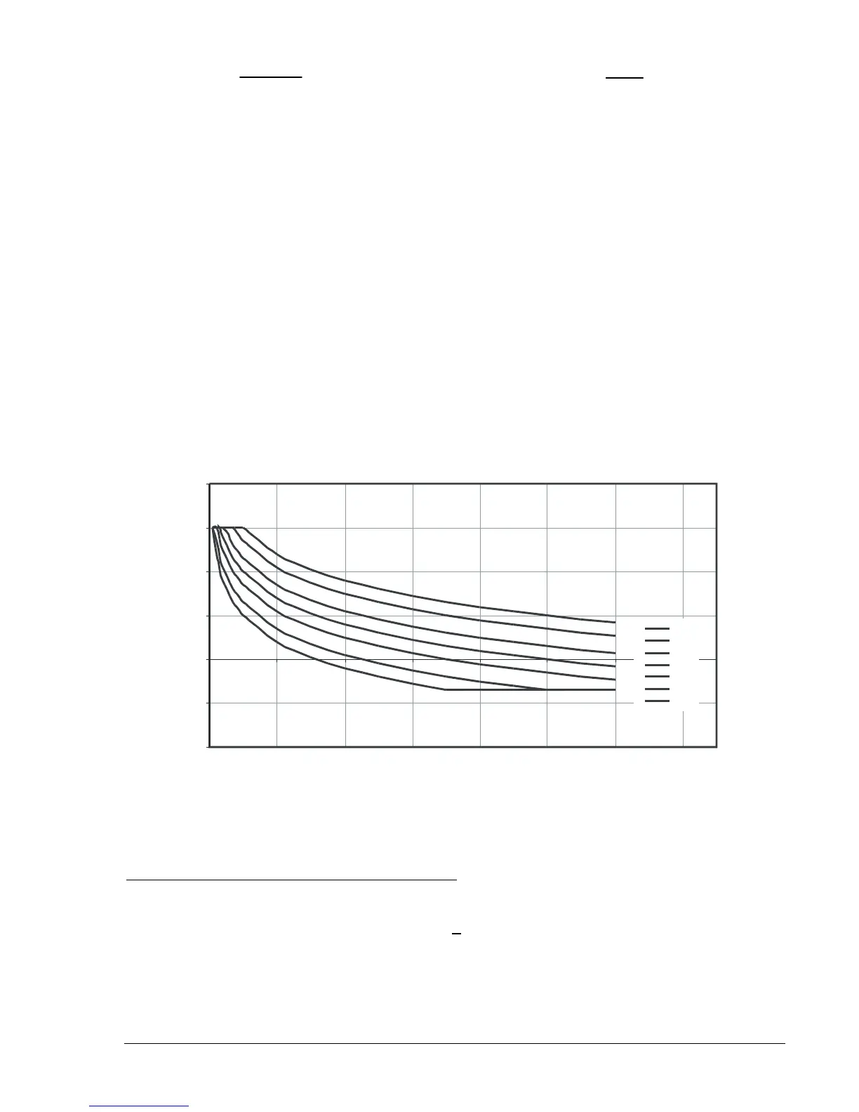
Figure 4-26 shows trip time for various time dials and multiples of pickup.
0.0
0.1
1.0
10.0
100.0
1000.0
10000.0
1 1.2 1.4 1.6 1.8 2 2.2 2.4
Multiples of Pickup
Trip Time in Seconds
9.9
5.0
2.0
1.0
0.5
0.2
0.1
D2871-40
08-14-03
Figure 4-26. Trip Time for Various Time Dials and Multiples of Pickup
BESTlogic Settings for Volts per Hertz Overexcitation
BESTlogic settings are made from the BESTlogic Function Element screen in BESTCOMS.
Figure 4-27
illustrates the BESTCOMS screen used to select BESTlogic settings for the overexcitation element. To
open the screen, select Voltage Protection from the S
creens pull-down menu and select the 24 tab. Then
select The BESTlogic button. Alternately, settings may be made using the SL-24 ASCII command.