4-18 BE1-951 Protection and Control 9328900990 Rev L
Table 4-6. BESTlogic Settings for Time Overcurrent
Function Range/Purpose Default
Mode
0 = Disabled
1 = Enabled
1 = 3-phase input neutral (51N, 151N only)
G = Ground input (51N, 151N only)
1
BLK Logic expression that disables function when TRUE. 0
Example 1. Make the following settings to the 151N element using BESTCOMS. Refer to
Figure 4-15.
Mode: Ground Input
BLK: IN1
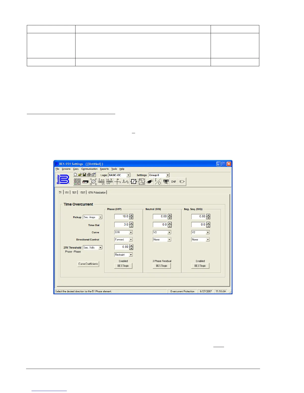
Operating Settings for Time Overcurrent
Operating settings are made using BESTCOMS.
Figure 4-16 illustrates the BESTCOMS screen used to
select operational settings for the Time Overcurrent element (the 51 element is shown). To open the
screen, select Overcurrent Protection from the S
creens pull-down menu and select either 51 or 151 tab.
Alternately, settings may be made using S<g>-51 and S<g>-151 ASCII commands or from the HMI
Screens 5.x.7.1 through 5.x.7.5 where x equals 1 for Setting Group 0, 2 for Setting Group 1, 3 for Setting
Group 2, and 4 for Setting Group 3.
Figure 4-16. Overcurrent Protection Screen, 51 Tab
The default unit of measure for the Pickup setting is secondary amps. Primary amps (Pri Amps), per unit
amps (Per U Amps), and percent amps (% Amps) can also be selected as the pickup setting unit of
measure. The unit of measure for the Time setting that represents the element's time delay defaults to
milliseconds. It is also selectable for seconds, minutes, and cycles.
At the top center of the screen is a pull-down menu labeled Logic. This menu allows viewing of the
BESTlogic settings for each preprogrammed logic scheme. A custom logic scheme must
be created and
selected in the Logic pull-down menu at the top of the screen before BESTlogic settings can be changed.
See Section 7, BESTlogic Programmable Logic. To the right of the Logic pull-down menu is a pull-down