4-46 BE1-951 Protection and Control 9328900990 Rev L
Example 1. Make the following operational settings to the 47 element. Refer to Figure 4-37.
Pickup: 50 Vpn secondary volts
Time: 50 ms
FREQUENCY PROTECTION
81 - Over/Under Frequency Protection
BE1-951 frequency protection consists of six independent elements that can be programmed for
underfrequency or overfrequency protection. Each element has an adjustable frequency setpoint and time
delay. The 81 elements share a common undervoltage inhibit setting. An over/underfrequency element is
shown in
Figure 4-38. Power system frequency is measured on the A phase voltage input for four-wire or
single-phase connections or the AB voltage input when in three-wire mode. Power system frequency is
measured on the optional auxiliary voltage input as well. When the applied voltage is greater than 10
volts, the BE1-951 measures the frequency. The measured frequency is the average of two cycles of
measurement.
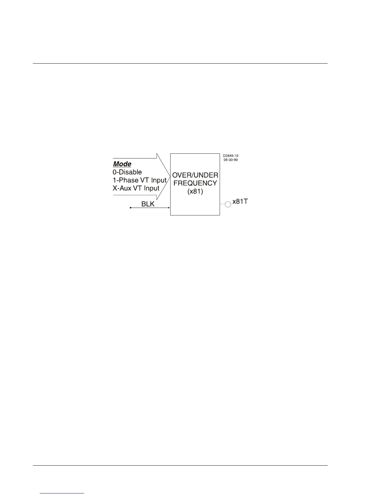
Figure 4-38. Over/Under Frequency Logic Block
Frequency element designations are 81, 181, 281, 381, 481, and 581. Each of the six elements has
identical inputs, outputs, and setting provisions.
Figure 4-39 illustrates the inputs and output of a
frequency element. A trip output (x81T) is provided on each element. The trip output becomes TRUE
when the monitored frequency decreases below (81U) or increases above (81O) the pickup setting and
the element timer times out.
The Block (BLK) input is used to disable protection. A BESTlogic expression is used to define how the
BLK input functions. When this expression is TRUE, the element is disabled by forcing the outputs to
logic 0 and resetting the timer. This feature functions in a similar way to the torque control contact of an
electromechanical relay.
An element is enabled or disabled by the Mode input. Three mode options are possible. Mode 0 disables
protection, mode 1 enables the element to monitor the frequency on VTP input, and mode x enables the
element to monitor the frequency on the VTX input. Security of your load-shedding scheme can be
enhanced by monitoring two independent VT circuits. See Section 8, Application Tips, for more
information. More information about logic mode selections is provided in the following BESTlogic Settings
for Over/Under Frequency paragraphs.
Pickup settings define the frequency setpoint and time delay and program the element for underfrequency
or overfrequency protection. The frequency setpoint defines the value of frequency that will initiate action
by an element. The time delay setting determines how long it takes for the trip output to become TRUE
once the measured frequency reaches the frequency setpoint. If three consecutive cycles of the
measured frequency have either decreased (81U) below or increased (81O) above the pickup threshold
and the timer has timed out, then the 81T will trip. If the timer has not timed out and the frequency
remains in the pickup range for the remainder of the time delay, the 81T will trip. If the monitored voltage
decreases below the user-defined setpoint, frequency protection is inhibited.
If the target is enabled for the element, the target reporting function will record a target for the appropriate
phase when the protective function trip output is TRUE and the fault recording function trip logic
expression is TRUE. See Section 6, Reporting and Alarm Functions, Fault Reporting, for more
information about target reporting.