4-40 BE1-951 Protection and Control 9328900990 Rev L
If the 60FL element trip logic is true and V block is enabled for 3VO blocking (N), the 27X/59X/159X
functions will be blocked if they are set to mode 2. For more information on the 60FL function, see the
paragraphs later in this section.
If the target is enabled for the 59X/159X element, the target reporting function will record a target when
the trip output is TRUE and the fault recording function trip logic expression is TRUE. See Section 6,
Reporting and Alarm Functions, Fault Reporting, for more information about target reporting. The
overcurrent elements have adaptable targets. If one is set for directional control, it will report a 67 target.
If one is set for non-directional control it will report a 59 target.
BESTlogic Settings for Auxiliary Undervoltage/Overvoltage
BESTlogic settings are made from the BESTlogic Function Element screen in BESTCOMS.
Figure 4-33
illustrates the BESTCOMS screen used to select BESTlogic settings for the auxiliary overvoltage element.
To open the BESTlogic Function Element screen for Auxiliary Under/Overvoltage elements, select
Voltage Protection from the S
creens pull-down menu. Then select the 27X or the 59X/159X tab.
Alternately; settings may be made using SL-59X, SL-159X, or SL-27X ASCII command.
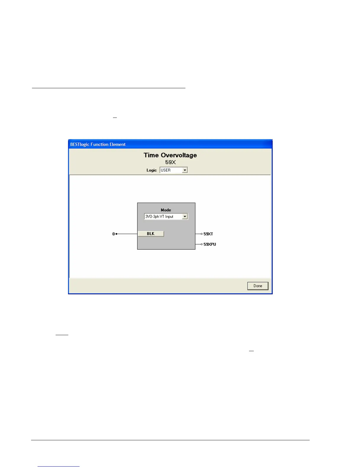
Figure 4-33. BESTlogic Function Element Screen, 59X
At the top center of the BESTlogic Function Element screen is a pull-down menu labeled Logic. This
menu allows viewing of the BESTlogic settings for each preprogrammed logic scheme. A custom logic
scheme must
be created and selected in the Logic pull-down menu at the top of the screen before
BESTlogic settings can be changed. See Section 7, BESTlogic Programmable Logic.
Enable the Under/Overvoltage function by selecting its mode of operation from the M
ode pull-down menu.
To connect the elements inputs, select the button for the corresponding input in the BESTlogic Function
Element screen. The BESTlogic Expression Builder screen will open. Select the expression type to be
used. Then, select the BESTlogic variable, or series of variables to be connected to the input. Select
Save when finished to return to the BESTlogic Function Element screen. For more details on the
BESTlogic Expression Builder, see Section 7, BESTlogic Programmable Logic. Select Done when the
settings have been completely edited.
BESTlogic settings for Auxiliary Undervoltage/Overvoltage are summarized in
Table 4-23.