4-16 BE1-951 Protection and Control 9328900990 Rev L
Range
Direction
N = Nondirectional
F = Forward Directional
R = Reverse Directional
N/A N/A N
∗ Time delays less than 10 cycles can be entered to the nearest 0.1 cycles from the front panel HMI. All
time delays can be entered to the nearest 0.01 cycles from the ASCII command interface. Time delays
entered in cycles are converted to milliseconds or seconds. Increment precision after conversion is limited
to that appropriate for each of those units of measure.
Example 1. Make the following settings to the 50TN element. Refer to
Figure 4-13.
Pickup: 2 secondary amps
Time: 10 seconds
If time delay settings are made in cycles, they are converted to seconds or milliseconds (per the nominal
frequency setting stored in EEPROM) before being stored. See Section 3, Input and Output Functions,
Power System Inputs, Current Measurement, for more information about this setting. If the nominal
frequency setting is being changed from the default (60 hertz) and time delay settings are being set in
cycles, the frequency setting should be entered and saved before making any time delay settings
changes.
Retrieving Instantaneous Overcurrent Status from the Relay
The status of each logic variable can be determined through the ASCII command interface using the RG-
STAT (report general-status) command. See Section 6, Reporting and Alarm Functions, General Status
Reporting, for more information. The status cannot be determined by using BESTCOMS.
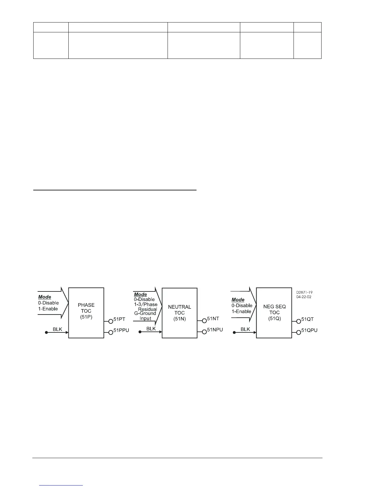
51 - Time Overcurrent Protection
BE1-951 relays have one element for phase (51P), two elements for neutral (51N and 151N), and one
element for negative-sequence (51Q) inverse time overcurrent protection.
Figure 4-14 shows the 51
elements. The 51N, 151N, and 51Q elements are identical in configuration. Each element has two
outputs: Pickup (PU) and Trip (T). A Block logic input is provided to disable the function. When this
expression is TRUE, the element is disabled by forcing the outputs to logic 0 and resetting the timers to
zero. This feature operates in a similar manner to the torque control contact of an electromechanical
relay.
Figure 4-14. Time Overcurrent Logic Blocks
Each inverse time overcurrent function has a mode, pickup, time dial, and curve setting. See Appendix A,
Time Overcurrent Characteristic Curves, for details on each of the curves available. To make the
protective element use integrated reset and emulate an electromechanical induction disk reset
characteristic, the user can append an R to the selected time current characteristic curve designation. An
available programmable curve can be used to create a custom curve by selecting coefficients in the
inverse time-characteristic equation.
When the measured current is above the pickup threshold, the pickup logic output is TRUE and inverse
timing is started according to the selected characteristic. If the current stays above pickup until the
element times out, the trip logic output becomes TRUE. If the current falls below the dropout ratio, which
is 95 percent, the function will either reset instantaneously or begin timing to reset depending on the
user's setting.
The phase overcurrent protective functions use the highest of the three measured phase currents. If the
current is above the pickup setting for any one phase, the pickup logic output is asserted. If the trip
condition is TRUE, the trip logic output is asserted.