12-2 BE1-951 Installation 9328900990 Rev L
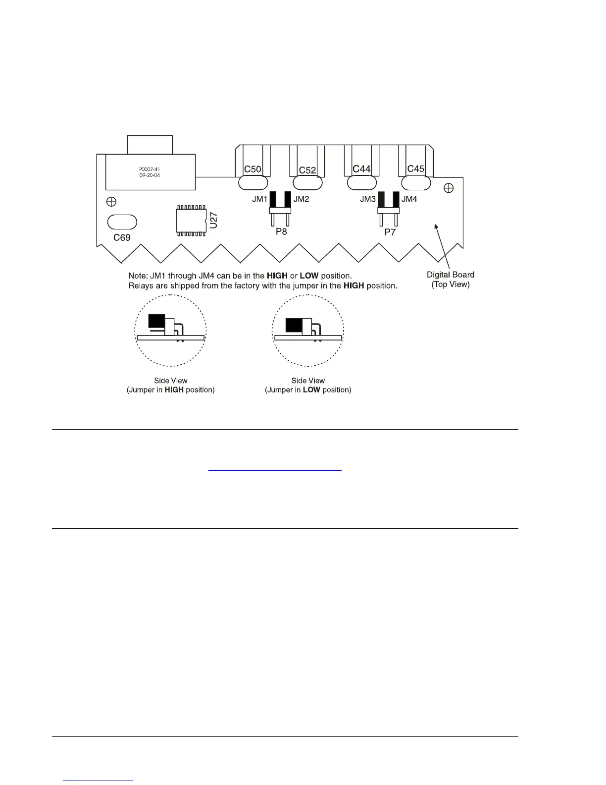
3. To select operation at the lower end of the control voltage range, install the jumper across the two
pins. Use care when removing and installing each jumper so that no components are damages.
4. When all jumpers are positioned for operation in the desired control voltage range, prepare to
place draw-out assembly back into the case.
5. Align the draw-out assembly with the case guides and slide the assembly into the case.
6. Tighten the screws.
Figure 12-1. Contact Sensing Jumper Locations
REGISTRATION OF RELAY
End users are encouraged to register their relays with Basler Electric. A label on each relay directs users
to complete registration on-line at
http://www.basler.com/register. Registering your relays(s) with Basler
Electric will give you Internet access to the latest BESTCOMS software and firmware updates for your
devices. In addition, registration also allows Basler Electric to contact you if a problem is found in the
design or manufacturing of our products that might affect you. The registration process only takes a few
minutes. Please have the serial number(s) of your relay(s) available when registering.
MOUNTING
Basler numeric relays are supplied in fully-drawout, S1 and H1 cases that can be mounted at any
convenient angle. The S1 case is normally panel mounted and has special mounting plates available for
adapting to existing cutouts. The H1 case can be adapted to a panel or rack for single or double case
mounting.
H1 Case Cutouts and Dimensions
H1 case dimensions are shown in
Figure 12-2. Adapter bracket 9289924100 allows a single relay to be
mounted in a 19-inch rack (see
Figure 12-3). A second adapter bracket (9289929100) performs the same
function but includes a cutout for an ABB FT switch (see
Figure 12-4). Two escutcheon plates are
available for panel mounting. Part number 9289900017 is used for panel mounting a single relay.
Escutcheon plate 9289900016 is used to panel mount two dovetailed relays. Mounting plate cutout and
drilling dimensions for a single H1 relay are shown in
Figure 12-5. If a single H1 relay is to be panel
mounted without an escutcheon plate, the cutout and drilling dimensions of
Figure 12-6 should be used.
Mounting plate cutout and drilling dimensions for two dovetailed H1 relays are shown in
Figure 12-7.
Figure 12-8 gives the cutout and drilling dimensions for panel mounting two dovetailed cases without an
escutcheon plate.