9328900990 Rev L BE1-951 Testing and Maintenance 13-5
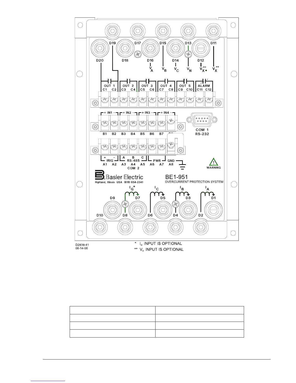
Figure 13-3. Rear Panel Terminal Connections (S1 Double-End Case)
Power Up
Purpose: To verify that the relay performs the power-up sequence.
Step 1: Apply voltage to the input power Terminals A6 and A7.
Table 13-1 shows the appropriate input
voltage for each relay style.
Table 13-1. Input Voltages
Style Number Voltage Input
xxN1Hx 48-125 Vac/dc
xxN2Hx 125-250 Vac/dc
xxN3Hx 24 Vdc
Step 2: Verify that the Power LED is ON, and that characters are displayed on the HMI display. Upon
power-up, the relay will perform a brief self-test.