9328900990 Rev L BE1-951 Testing and Maintenance 13-27
Step 5: Slowly increase the A-phase current until OUT3 (51Q pickup indicator) closes (3 x A-phase
value). Verify that pickup occurs within the specified accuracy listed in
Table 13-29. Slowly
decrease the applied current until OUT3 opens. Dropout should occur at 93 to 97 percent of
pickup. Verify the 51Q target on the HMI. Verify the pickup accuracy of the middle and upper
pickup settings for your sensing type.
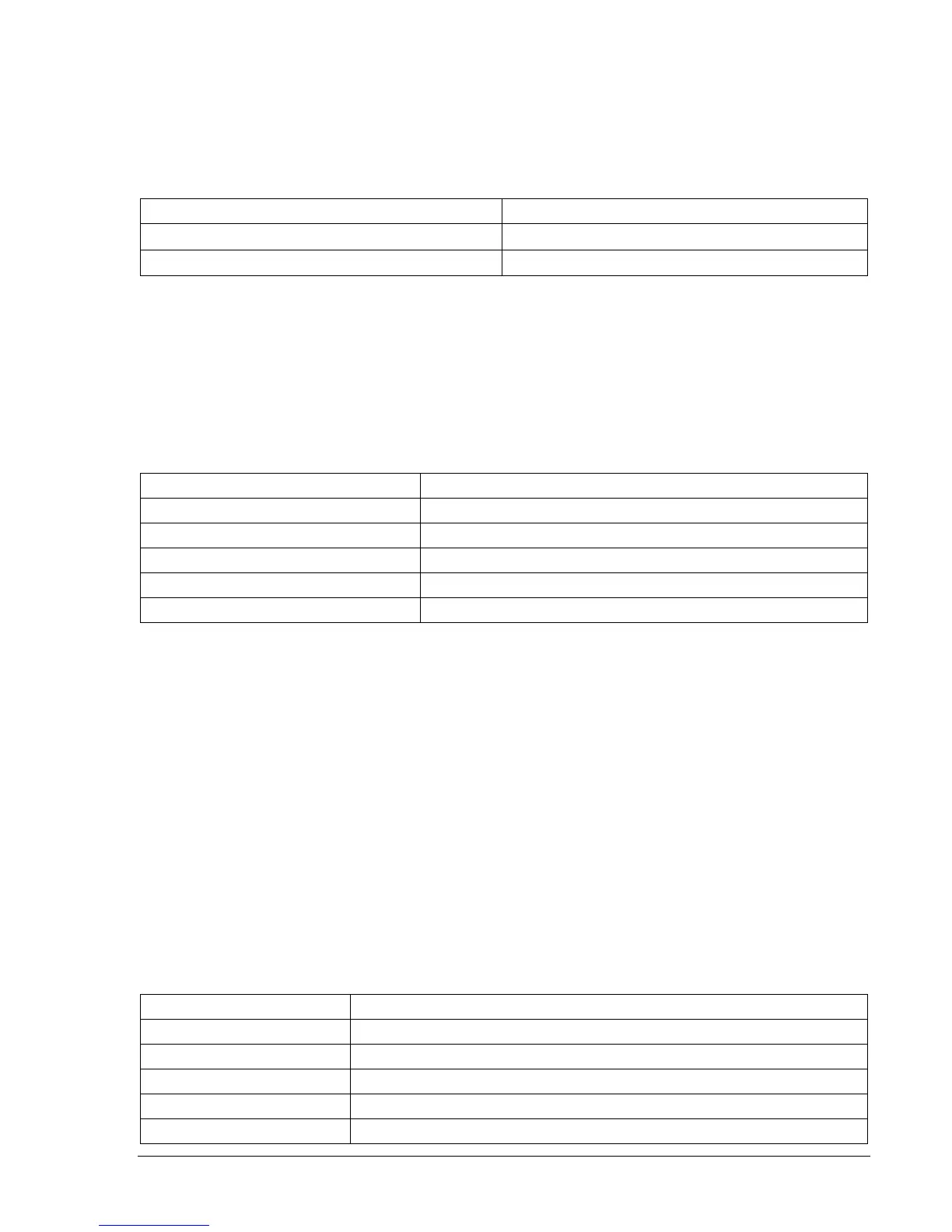
Table 13-29. 51Q Element Accuracy
Sensing Type Pickup Accuracy
A or B (1 A)
±3% or ±15mA
D, E, or F (5 A)
±3% or ±75mA
Step 6: (Optional.) Repeat Steps 3 through 5 for phase B (Terminals D3 and D4) and phase C
(Terminals D5 and D6). To test independent ground input IG, gain access and transmit SL-
51N=G,0 exit and save. Apply test current to Terminals D7 and D8, while monitoring OUT2 and
repeat Step 4. Verify 51G target on the HMI.
Step 7: (Optional.) Repeat Steps 1 through 4 and Step 6, IG input, for the 151N element. Overwrite the
51 commands entered in Step 2 with the commands of
Table 13-30.
Table 13-30. 151N Pickup Test Commands
Command Purpose
A= Gains write access.
SL-151N=G,0 Enables 151N, disables blocking.
SL-VO2=151NT Enables OUT2 to close for 151N trip.
SG-TRIGGER=151NT,151NPU,0 Enable 151NT or 151NPU to log and trigger fault recording.
EXIT;Y Exit and save settings.
Step 8: (Optional.) Repeat Steps 1 through 7 for the 51P, 51N, and 151N elements in Setting Groups 1,
2, and 3. Before testing settings in other setting groups, a setting group must be selected using
the CS/CO-GROUP commands. To activate Setting Group 1, CS-GROUP=1 would be entered
to select Setting Group 1 and CO-GROUP=1 would be entered to make Setting Group 1 active.
Also, the pickup settings made in Step 3 (
Table 13-27) must be changed to specify the setting
group being tested. To test settings in Group 1, replace the 0 in the S0-x51 commands with a 1
(S1-x51).
Voltage Restraint/Control Time Overcurrent
Purpose: To verify the operating accuracy of the 27R (Restraint and Control) for the phase time
overcurrent function.
Reference Commands: S<g>-27R, SL-51, RG-STAT 51/27R - Voltage "Control" Pickup and Dropout
Verification
Step 1: To prepare the 51P element for testing, transmit the commands in
Table 13-31 to the relay.
Reset targets.
Table 13-31. 51P Pickup Test Commands
Command Purpose
A= Gains write access.
SL-N=NONE Zero out custom logic settings. Overwrite with LOGIC=NONE settings.
Y Confirm overwrite.
SL-N=51/27R/C Sets custom logic name.
SG-VTP=1,4W,PN,PN Set VT phase voltage parameters.