13-28 BE1-951 Testing and Maintenance 9328900990 Rev L
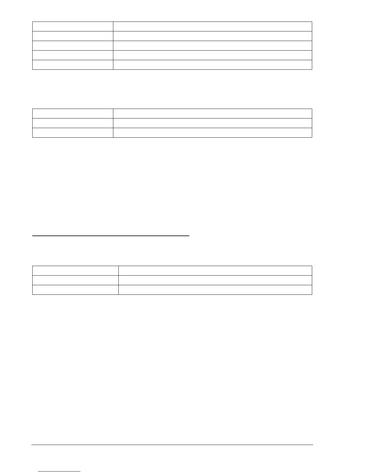
Command Purpose
SL-51P=1,0 Enables 51P and disables blocking.
SL-VO1=51PT Enables OUT1 to close for 51PT trip.
SG-CT=1 Sets P, N CT ratio at 1:1
EXIT;Y Exit and save settings.
Step 2: Using
Table 13-32 as a guide, transmit the 51/27R setting commands to the relay.
Table 13-32. Example of 51/27R Settings
Operating Settings Purpose
S0-51P=2.0,0,V2,N Sets 51P PU at 2 amps, TD = 0, Time Curve = V2, non-directional.
S0-27R=100,C Set 27R to 100 volts, 51P to Voltage Control.
Step 3: Connect and apply 120 Vac, three-phase, 50 or 60 hertz voltage source (depending on users
nominal frequency) to Terminals C13 (A-phase), C14 (B-phase), C15 (C-phase), and C16
(Neutral). Connect a variable ac current source to Terminals D1 (A-phase polarity) and D2 (A-
phase non-polarity). Refer to
Figure 13-1 for terminal locations.
Step 4: Apply 2 amps of A-phase current and slowly reduce A-phase voltage until OUT1 closes.
Increase A-phase voltage until OUT1 just drops out. Pickup will occur within ±2 percent or 1 volt
of the of the 27R voltage setting. Dropout will occur at 102 to 103% or actual pickup.
Step 5: Repeat Steps 2 and 3 for B-phase current (D3 and D4) while varying B-phase voltage and C-
phase current (D5 and D6) while varying C-phase voltage.
Step 6: (Optional.) Repeat Steps 2 through 5 for Setting Groups 1, 2, and 3.
51/27R-Voltage "Restraint" Pickup and Dropout Verification
Step 1: Using
Table 13-33 as a guide, transmit the 51/27R setting commands to the relay.
Table 13-33. 51/27R Settings
Operating Settings Purpose
S0-51P=2.0,0,V2,N Sets 51P PU at 2 amps, TD = 0, Time Curve = V2, non-directional.
S0-27R=100,R Set 27R to 100 volts, 51P to Voltage Restraint.
Step 2: Connect and apply 120 Vac, three-phase, 50 or 60 hertz voltage source (depending on users
nominal frequency) to Terminals C13 (A-phase), C14 (B-phase), C15 (C-phase), and C16
(Neutral). Connect a variable ac current source to Terminals D1 (A-phase polarity) and D2 (A-
phase non-polarity). Refer to
Figure 13-1 for terminal locations.
Step 3: Adjust the A-phase voltage to VR setting (100 volts). Apply and slowly increase A-phase current
until OUT1 closes. Decrease A-phase current until OUT1 just drops out. Pickup will occur within
±2 percent of the 51P pickup setting. Dropout will occur at 93 to 97% of actual pickup.
Step 4: Adjust the A-phase voltage to ½ VR setting (50 volts). Apply and slowly increase A-phase
current until OUT1 closes. Decrease A-phase current until OUT1 just drops out. Pickup will
occur at ½ the 51P pickup setting (1 amp ±2 percent). Dropout will occur at 93 to 97% of actual
pickup. See Section 4, Protection and Control, Overcurrent Protection, for a graphical
explanation of 51P Pickup Level Compensation.
Step 5: Repeat Steps 2 and 3 for B-phase current (D3 and D4) while varying B-phase voltage and C-
phase current (D5 and D6) while varying C-phase voltage.
Step 6: (Optional.) Repeat Steps 1 through 5 for Setting Groups 1, 2, and 3.