9328900990 Rev L BE1-951 Human-Machine Interface 10-1
SECTION 10 • HUMAN-MACHINE INTERFACE
INTRODUCTION
This section describes the BE1-951 human-machine interface (HMI) and illustrates the front panel display
menu tree branches.
FRONT PANEL DISPLAY
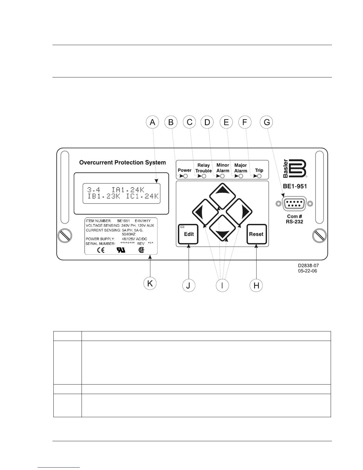
Figure 10-1 shows the HMI components of a BE1-951 in an H1 case. Table 10-1, following Figure 10-1,
describes each HMI component. S1 style relays have the same HMI components with a different layout.
Figure 10-1. Front Panel, H1 Case
Table 10-1. Front Panel HMI Descriptions
Locator Description
A
Display – Two line by 16-character liquid crystal display (LCD) with backlighting. The LCD is
the primary source for obtaining information from the relay or when locally setting the relay.
Information such as targets, metering values, demand values, communication parameters,
the active logic scheme name, and diagnostic information is provided by the LCD.
Information and settings are displayed in a menu with six branches. The Menu Tree
subsection provides more information about the menu branches.
B Power Indicator – This green LED lights when operating power is applied to the relay.
C
Relay Trouble Indicator – This red LED lights momentarily during start-up and lights
continuously when a relay failure is detected. Section 6, Reporting and Alarm Functions,
provides a complete description of all relay failure alarm diagnostics.