9328900990 Rev L BE1-951 Testing and Maintenance 13-9
Power Reading Verification
Step 1: Use the same voltage connections as in the previous test, polarity voltage jumpered to C13, 14,
and 15, neutral tied to C16. Use the same current connection as in Steps 3 and 4 of Current
Circuit Verification; that is, polarity current in 1 out 8 with 2 and 3, 4 and 5, 6 and 7 jumpered
together.
Step 2: Apply 100 volts at angle 0 degrees and 1 or 5 amps (depending on the current rating) at angle 0
degrees to the relay. Verify the accuracy of the power reading by transmitting the M command
to the relay. Power should be 1.5 kw ±1.0% and reactive should read near 0 vars. HMI Screen
3.8 can also be monitored to verify power and reactive readings. The apparent power should be
1.5 kVA ±1.0% at unity power factor. Apparent power can also be viewed on HMI Screen 3.9.
Step 3: Reverse the current polarity and apply the same values as in Step 2. Note that the power
reading is -1.5 kw, which indicates "power in" to the zone being protected.
Step 4: Return the current polarity back to Step 1 position. Apply 100 volts at angle 0 degrees and 5
amps at angle -90 degrees (I lag E by 90 degrees) to the relay, and verify reactive power
accuracy by transmitting the M command to the relay. Power should be nearly 0 kw, and
reactive should read 1.5 kvar ±1.0%. HMI Screen 3.8 can also be monitored to verify power and
reactive values. Apparent power and power factor can also be viewed on HMI Screen 3.9. Note
power factor reads near 0 with a negative sign indicating a lagging power factor angle.
Step 5: Reverse the current polarity and apply the same values as in Step 4. Note that the reactive
power reading is -1.5 kvar, which indicates reactive power in to the device being protected. Also
note that the power factor angle is near 0 with a positive sign indicating a leading power factor
angle.
Step 6: Repeat Step 2 and 4 for current values of 10 and 20 amps. Corresponding power reading
should be 3 kw/kvar and 6 kw /kvar ±1.0%.
Auxiliary Voltage Input Verification - VX and VX 3
rd
(Fundamental and Third Harmonic)
Step 1: Connect relay terminals C17 (polarity) and C18 to a 60 hertz ac voltage source.
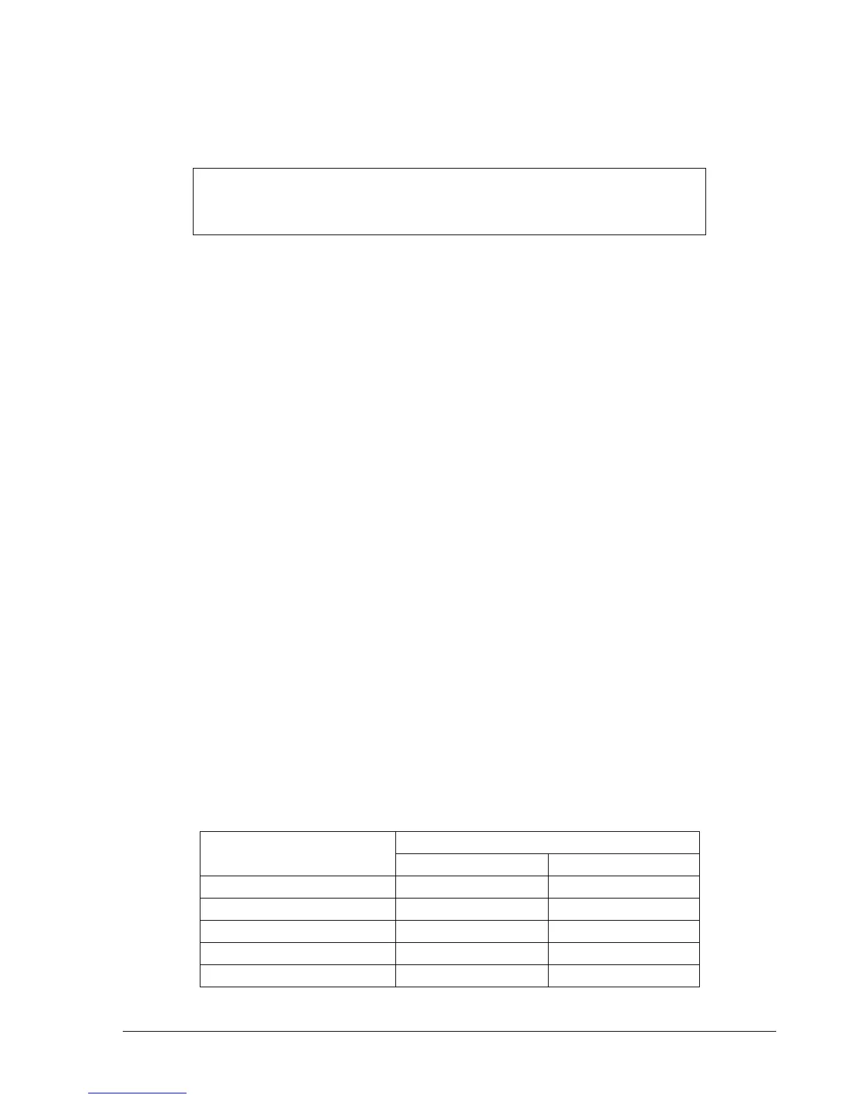
Step 2: Apply the voltage values listed in
Table 13-5 and verify voltage-measuring accuracy by
transmitting the M-V command to the relay. HMI Screens 3.3, VX can also be monitored to
verify voltage measurements.
Step 3: Connect relay Terminals C17 (polarity) and C18 to a 180 hertz (third harmonic) ac voltage
source.
Step 4: Apply the voltage values listed in
Table 13-5 and verify voltage-measuring accuracy by
transmitting the M command to the relay. HMI Screen 3.3, VX can also be monitored to verify
voltage measurements.
Table 13-5. Aux Voltage Circuit Verification VX & VX 3
rd
Values
Measured Voltage
Applied Voltage
Lower Limit Upper Limit
5 volts 4.95 V 5.05 V
20 volts 19.8 V 20.2 V
60 volts 59.4 V 60.6 V
80 volts 79.2 V 80.8 V
120 volts 118.8 V 121.2 V
NOTE
Power readings in this procedure are based on a 5 amp relay; for 1 amp values,
divide by 5.