9328900990 Rev L BE1-951 Application 8-47
in for these logic settings. These miscellaneous logic settings must be reviewed to ensure desired
performance for these functions.
Table 8-25. Miscellaneous Logic Expressions
Command Reference
SA-RESET Section 6, Reporting and Alarm Functions, Alarms Function
SB-DUTY Section 6, Reporting and Alarm Functions, Breaker Monitoring
SB-LOGIC Section 6, Reporting and Alarm Functions, Breaker Monitoring
SG-TARG Section 6, Reporting and Alarm Functions, Fault Reporting
SG-TRIGGER Section 6, Reporting and Alarm Functions, Fault Reporting
SP-79ZONE Section 4, Protection and Control
APPLICATION TIPS
Trip Circuit and Voltage Monitor
This application tip is intended for feeder applications using FDR-W-IL logic along with BUS and BACKUP
schemes for protection.
OUT1 has a built-in trip circuit voltage and continuity monitor that drives logic variable OUT1MON. This
variable can be used to improve breaker failure logic or to automatically enhance security during testing.
If the relay detects a loss of voltage or continuity in the breaker trip circuit, it's possible to reduce fault
clearing time by bypassing the breaker failure timer. Since feeder relay "Out of Service" and breaker
failure are covered by different backup actions, it is desirable to reduce common mode failure
mechanisms. It is recommended that the feeder breaker and feeder protection circuits be supplied by
separate control power fuses or breakers. The equation for the breaker failure trip logic (VO5) can be
modified by ORing the breaker failure initiate with the expression VO10*OUT1MON. VO10 is designated
in the FDR-W-IL preprogrammed logic schemes as the breaker failure initiate expression. Example 1
shows how the BFT logic expression is modified. It's important that the breaker failure timer bypass logic
also be disabled in test mode. Example 2 shows the expression for blocking the upstream instantaneous
element.
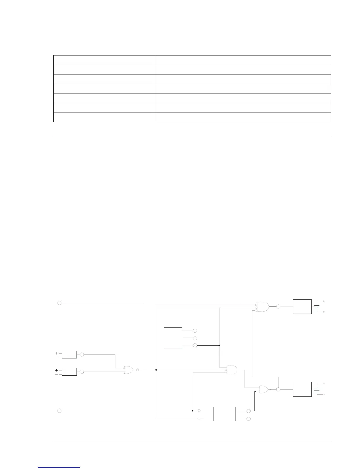
Figure 8-14 illustrates how the trip circuit continuity monitor can be used in breaker failure logic.
Example 1. Breaker Failure Trip Expression: SL-VO5=BFT+VO10*OUT1MON*/VO15
Example 2. Block Upstream Instantaneous Expression: SL-VO4=VO12*/VO5*/OUT1MON*/VO15
OUTPUT
LOGIC
OUT5
VO5
Breaker
Failure Trip
BREAKER
FAILURE
(BF)
BLK
INI
BFT
BFPU
VO10
Breaker Failure
Initiate Ex
ression
TEST MODE
VO15
IN4 TEST
MODE
OPTO
343 TEST
MODE
OPTO
Test Mode Enable Switch
1 = Normal, 0 = Enabled
Test Mode Enable Virtual Switch
1 = Enabled, 0 = Normal
D2861-0
07-21-99
OUT4
OUTPUT
LOGIC
oc
pstream
Instantaneous
VO4
VO12
Protective
Pickup Expression
ALARMS
ALMMI
N
OUT1MON
ALMMAJ
Figure 8-14. Trip Circuit Continuity and Voltage Monitor