13-46 BE1-951 Testing and Maintenance 9328900990 Rev L
Synchronism Check (25)
Purpose: To verify the operation of the Sync Check (25) function.
Reference Commands: SL-25, SL-V0.
25VM - VTP Phase and VTX Live Voltage, Dead Voltage Pickup Test
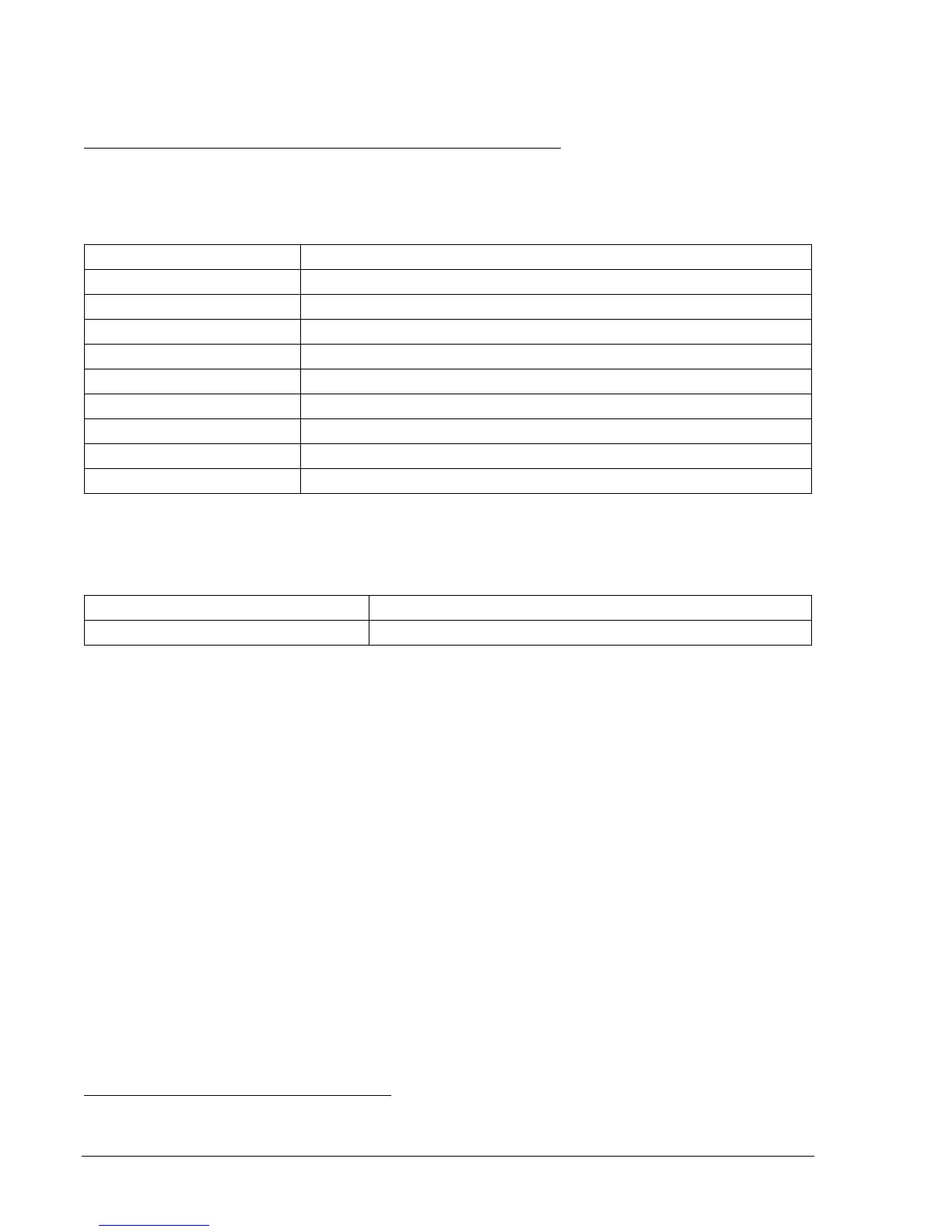
Step 1: Prepare the 25 function block for testing by transmitting the commands in
Table 13-67 to the
relay.
Table 13-67. Sync Check Pickup Test Commands
Command Purpose
A= Gains write access.
SL-N=NONE Zero out custom logic settings. Overwrite with LOGIC=NONE settings.
Y Confirm overwrite.
SL-N=25 Sets 25 as custom logic name.
SG-VTP=1,4W,PN,PN Set VT phase voltage parameters.
SG-VTX=1,AN Set VT auxiliary voltage parameters.
SL-25=1,0 Enable 25 function.
SL-VO1=25VM1 Enables OUT1 to close for 25VM1.
EXIT;Y Exit and save settings.
Step 2: Using
Table 13-68 as a guide, transmit the setting commands to the relay.
Table 13-68. Sync Check Voltage Monitor Pickup Settings
Sync Check VM Pickup Settings Purpose
S0-25VM=95,55,0,123,123 Sets LV = 95, DV = 55, TD = 50, VM1 = 123, VM2 = 123.
Step 3: Prepare to monitor the 25VM function operation. Operation can be verified by monitoring OUT1.
Step 4: Connect relay Terminals C13 (A-phase), C14 (B-phase), and C15 (C-phase) together. Apply a
single phase, 0 Vac, 50 or 60 hertz ac voltage source (Line VT Phase) to the three jumpered
terminals and the Neutral Terminal (C16).
Step 5: OUT 1 should be closed. Slowly increase the Line voltage until OUT1 opens (55 volts). Dropout
should occur within ±2 percent or 1 volt of the Dead Voltage setting. Lower the voltage until
OUT1 closes. Pickup should be between 97 to 98% of the actual dropout value. Increase the
voltage until OUT1 opens. Continue to increase the voltage until OUT1 closes (95 volts). Pickup
should occur within ±2 percent or 1 volt of the Hot Voltage setting. Lower the voltage until OUT1
opens. Dropout should occur between 97 and 98% of the actual pickup value. Remove voltage
source 1.
Step 6: Connect a second single-phase 50 or 60-hertz voltage source (Auxiliary VX) to relay Terminals
C17 (polarity) and C18 (non-polarity). Apply 0 vac.
Step 7: Output 1 should be closed. Slowly increase the Auxiliary voltage until OUT1 opens (55 volts).
Dropout should occur within ±2 percent or 1 volt of the Dead Voltage setting. Lower the voltage
until OUT1 closes. Pickup should be between 97 to 98% of the actual dropout value. Increase
the voltage until OUT1 opens. Continue to increase the voltage until OUT1 closes (95 volts).
Pickup should occur within ±2 percent or 1 volt of the Hot Voltage setting. Lower the voltage
until OUT1 opens. Dropout should occur between 97 and 98% of the actual pickup value.
Step 8: (Optional.) Repeat Steps 2 through 7 for Setting Groups 1, 2, and 3.
25VM Live/Dead Dropout Timing Verification
Step 1: Using
Table 13-69 as a guide, transmit the setting commands to the relay.