3-6 BE1-951 Input and Output Functions 9328900990 Rev L
Energizing levels for the contact sensing inputs are jumper selectable for a minimum of approximately 5
Vdc for 24 Vdc nominal sensing voltages, 26 Vdc for 48 Vdc nominal sensing voltages, or 69 Vdc for 125
Vdc nominal sensing voltages. See Table 3-2 for the control voltage ranges.
Table 3-2. Contact Sensing Turn-On Voltage
Turn-On Voltage Range
Nominal Control Voltage
Jumper Installed
(Low Position)
Jumper Not Installed
(High Position)
24 Vdc N/A Approx. 5 Vdc
48/125 Vac or Vdc 26 – 38 Vac or Vdc 69 – 100 Vac or Vdc
125/250 Vac or Vdc 69 – 100 Vac or Vdc 138 – 200 Vac or Vdc
Each BE1-951 is delivered without the contact-sensing jumpers installed for operation in the higher end of
the control voltage range. If the contact sensing inputs are to be operated at the lower end of the control
voltage range, the jumpers must be installed. See Section 12, Installation, for details on how to set the
jumper positions in the contact sensing input circuits.
The contact sensing inputs circuits are polarity sensitive. When an ac wetting voltage is applied, the input
signal is half-wave rectified by the opto-isolator diodes. The contact sensing inputs drive BESTLOGIC
variables IN1, IN2, IN3, and IN4. Each contact sensing input is completely programmable so meaningful
labels can be assigned to each input and the logic-high and logic-low states. Section 7, BESTLOGIC
Programmable Logic, provides more information about using contact sensing inputs in your
programmable logic scheme.
Digital Input Conditioning Function
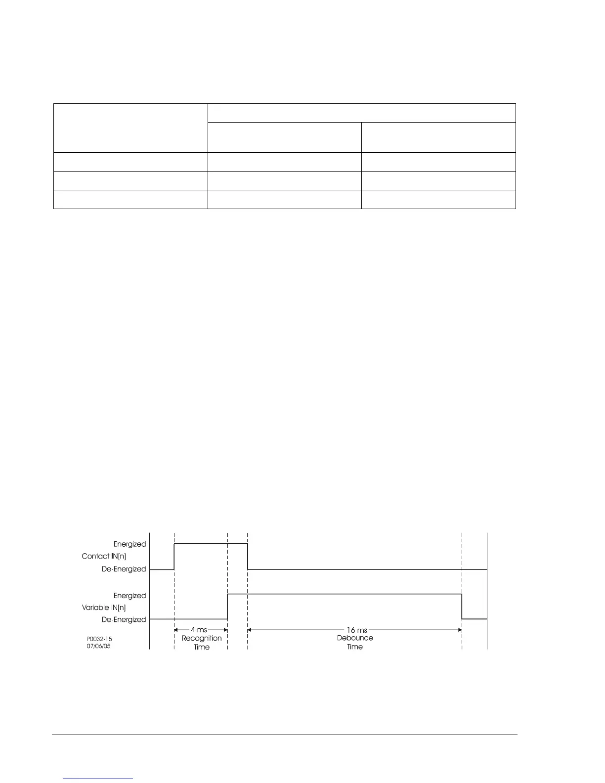
Status of the contact sensing inputs is checked 12 times per cycle. (See Figure 3-3.) When operating on
a 60-hertz power system, the result is the input status being sampled every 1.4 milliseconds (1.6
milliseconds on 50 hertz systems). User-settable digital contact recognition and debounce timers
condition the signals applied to the inputs. These parameters can be adjusted to obtain the optimum
compromise between speed and security for a specific application. Digital input conditioning is evaluated
every quarter cycle.
If the sampled status of a monitored contact is detected as energized for the recognition time, the logic
variable changes from a de-energized (logic 0 or FALSE) state to an energized (logic 1 or TRUE) state.
Once contact closure is recognized, the logic variable remains in the energized state until the sampled
status of the monitored contact is detected to be de-energized for a period that is longer than the
debounce time. At this point, the logic variable will change from an energized (logic 1 or TRUE) state to a
de-energized (logic 0 or FALSE) state.
Figure 3-3. Digital Input Conditioning Timing Diagram