9328900990 Rev L BE1-951 Protection and Control 4-75
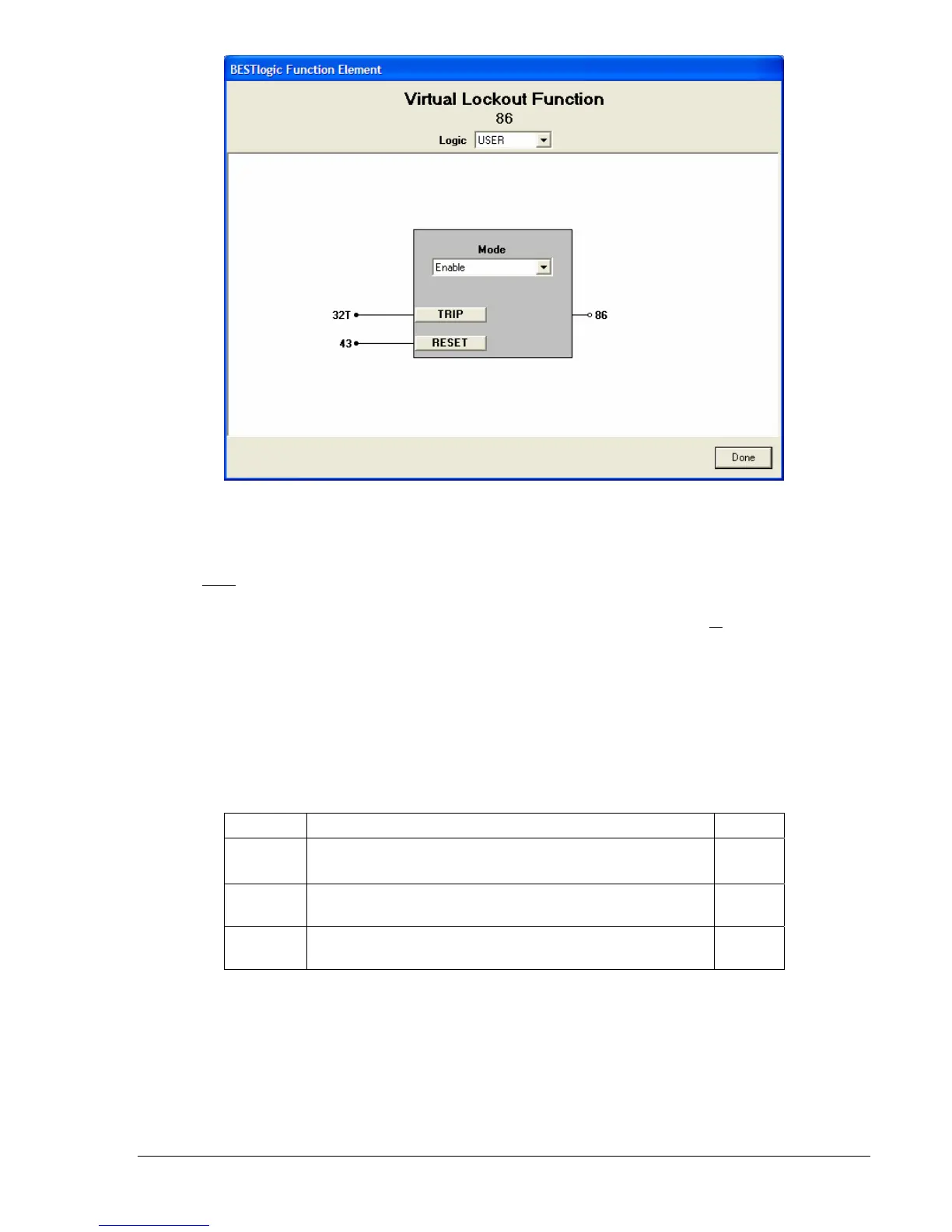
Figure 4-70. BESTlogic Function Element Screen, 86
At the top center of the BESTlogic Function Element screen is a pull-down menu labeled Logic. This
menu allows viewing of the BESTlogic settings for each preprogrammed logic scheme. A custom logic
scheme must
be created and selected in the Logic pull-down menu at the top of the screen before
BESTlogic settings can be changed. See Section 7, BESTlogic Programmable Logic.
Enable the lockout protection element by selecting its mode of operation from the M
ode pull-down menu.
To connect the element's inputs, select the button for the corresponding input in the BESTlogic Function
Element screen. The BESTlogic Expression Builder screen will open. Select the expression type to be
used. Then, select the BESTlogic variable, or series of variables to be connected to the input. Select
Save when finished to return to the BESTlogic Function Element Screen. For more details on the
BESTlogic Expression Builder, see Section 7, BESTlogic Programmable Logic. Select Done when the
settings have been completely edited.
Table 4-43 summarizes the BESTlogic settings for Virtual Lockout.
Table 4-43. BESTlogic Settings for Virtual Lockout
Function Range/Purpose Default
Mode
0 = Disable
1 = Enable
0
Trip
Logic expression that determines when and how the
element will trip.
0
Reset
Logic expression that determines when and how the
element will be reset.
0
Example 1. Make the following BESTlogic settings to the lockout function. Refer to
Figure 4-70.
Mode: Enable
Trip: 32T
Reset: 43