4-8 BE1-951 Protection and Control 9328900990 Rev L
Example 1:
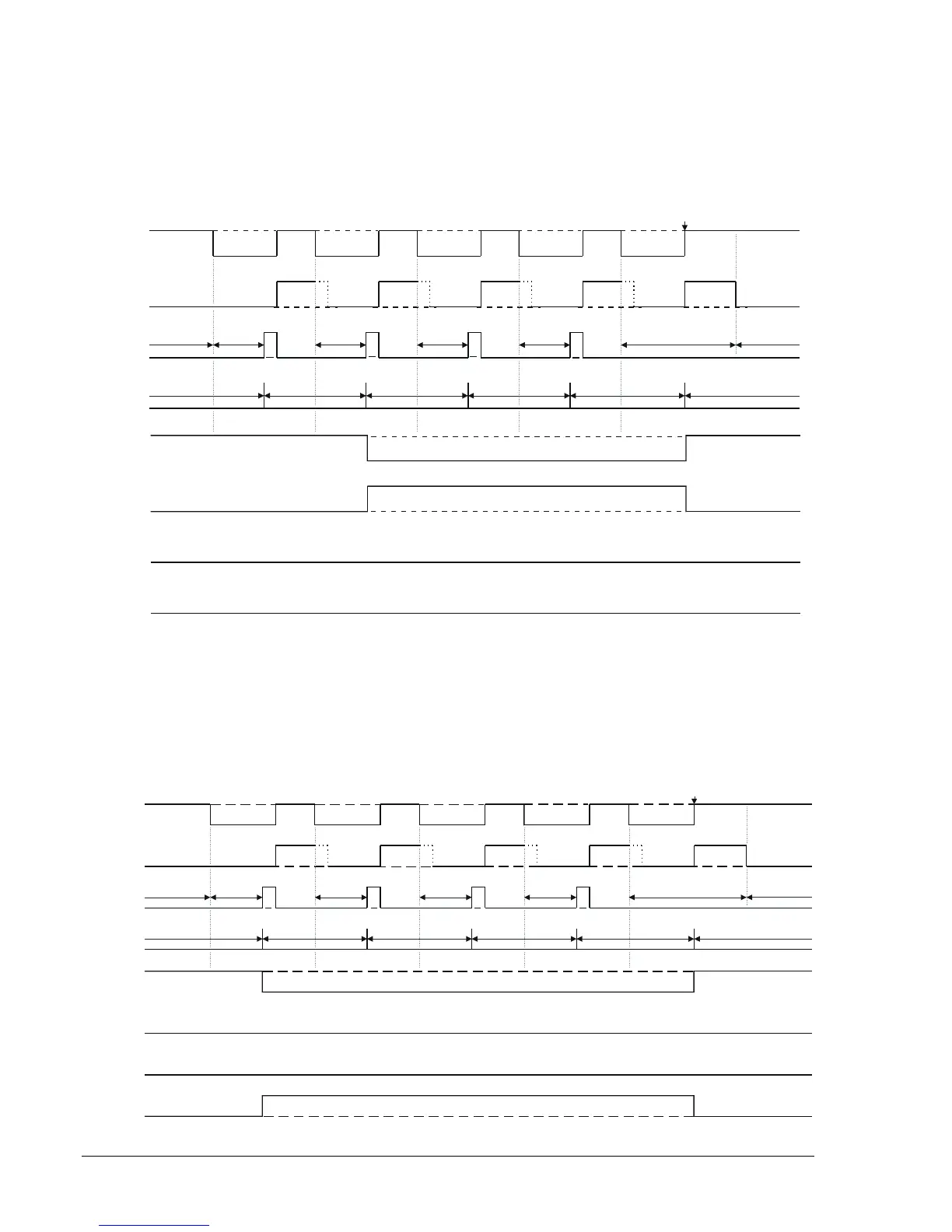
In most common practices, only two setting groups would be used for emulating circuit recloser in a fuse
saving scheme (a "fast" curve and a "slow" curve). The settings below call for using Setting Group 0
during normal operation, Setting Group 1 after reclose 2, and remain in Setting Group 1 until the breaker
closed from lockout. The active group would return to Setting Group 0 when the recloser went to reset if
any of the close operations prior to lockout was successful. Setting Groups 2 and 3 are not used (the 51P
element is monitored by settings, but the switch-to threshold and switch-to time delay are zero, so a
switch to Setting Group 2 or 3 never occurs). Refer to
Figure 4-7.
Manual Close
79RTD 79RTD 79RTD 79RTD 79RTD
RESET
791TD 792TD 793TD 794TD LOCKOUT RESET
1 2345 1
Closed
BREAKER STATUS
Open
RESET
TIMER
79C
Recloser
STEP
SG0
SG1
SG2
SG3
P0002-07
10-14-03
Figure 4-7. Example 1, Change Group on Recloser Shot
Example 2:
This example illustrates an error in setting the automatic group control. As mentioned above, the settings
group changes via SP-GROUP parameter <prot_ele> = 791, 792, 793, or 794 can only raise the setting
group number. For example, the following would change to Setting Group 3 after reclose shot 1 and the
setting group would remain in Setting Group 3 until RESET is reached or breaker closed from lockout, at
which time the setting group returns to Setting Group 0. The relay would never use Setting Group 1 or 2.
Refer to
Figure 4-8.
Closed
BREAKER STATUS
Open
79RTD 79RTD 79RTD 79RTD 79RTD
RESET
791TD 792TD 793TD 794TD LOCKOUT RESET
Manual Close
1 234 5 1
RESET
TIMER
79C
Recloser
STEP
SG0
SG1
SG2
SG3
P0002-08
10-14-03
Figure 4-8. Example 2, Error in Setting Group Control by Recloser Shot