4-6 BE1-951 Protection and Control 9328900990 Rev L
nominal relays) after the switch-to time. This is used in the example application for cold load pickup,
below.
If the monitored element is 791, 792, 793, 794, the switch-to time, switch-to threshold, return time, and
return threshold are ignored and the setting group is based upon the status for the reclose step. This
method of controlling setting groups will be covered further below.
If a group's switch-to threshold is zero and the groups switch-to time delay is 0 and the monitored element
is any overcurrent element (i.e., not 791, 792, 793, or 794), then the relay will never automatically switch-
to that setting group.
There are five settings for each group that are used for automatic control. Each group has a switch to
threshold and time delay, a return threshold and time delay, and a monitored element. The switch to and
return thresholds are a percentage of the SG0 pickup setting for the monitored element. The monitored
element can be any of the 51 protective functions. Thus, if you wish to switch settings based upon
loading, you could set it to monitor 51P. If you wish to switch settings based upon unbalance, you could
set it to monitor 51N, 151N, or 51Q. When the monitored element is 51P, any one phase must be above
the switch to threshold for the switch to time delay for the criteria to be met. All phases must be below the
return threshold for the return time delay for the return criteria to be met.
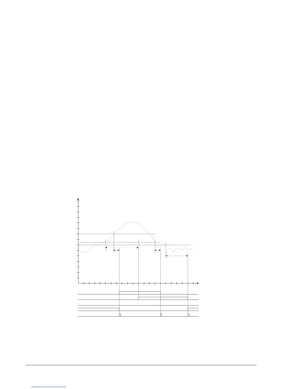
Figure 4-5 shows an example of using the automatic setting group selection settings to change settings
groups based upon loading. Note that the AUTO input must be at a TRUE logic state in order to allow the
automatic logic to operate. At time = 0, current begins to increase. When current reaches 75 percent of
pickup, Setting Group 2 begins timing (30 minutes). When current reaches 90 percent of pickup, Setting
Group 3 begins timing (5 minutes). After 5 minutes, at time = 37, with the current still above Setting Group
3 threshold, Setting Group 3 becomes active and the setting group change output pulses. At time = 55,
Setting Group 2 timer times out but no setting group change occurs because a higher setting group takes
precedence. The faint dashed line for SG2, between time = 55 and 75 shows that Setting Group 2 would
be active except for Setting Group 3. Current decreases to 75 percent at time = 70 and Setting Group 3
return timer begins timing. Current varies but stays below 75 percent for 5 minutes and at time = 75,
Setting Group 2 becomes active and the setting change output pulses. After 20 minutes, Setting Group 0
becomes active and the setting change output pulses.
Load
Current
as % of S0-51
<pickup>
0
9
0
8
0
7
0
6
05040
3
0
20
1
0
10
0
4
0
3
0
2
0
1
0
10
0
9
0
8
0
7
0
6
0
5
0
12
0
11
0
14
0
13
0
15
0
TIME
(MINUTES
3
0
5
2
0
5
SP-GROUP3=5,90,5,75,51P
SP-GROUP2=30,75,20,70,51P
SG3
SG2
SG1
SG0
D2837-23
05-05-04
Figure 4-5. Automatic Operation Based on Load Change
This function can also be used to automatically change the active setting group for cold load pickup
conditions. If the switch to threshold for a group is set to 0%, the function will switch to that group when
there is no current flow for the time delay period indicating that the breaker is open or the circuit source is
out of service. The threshold for this is 10% nominal rating of the relay current input.