4-42 BE1-951 Protection and Control 9328900990 Rev L
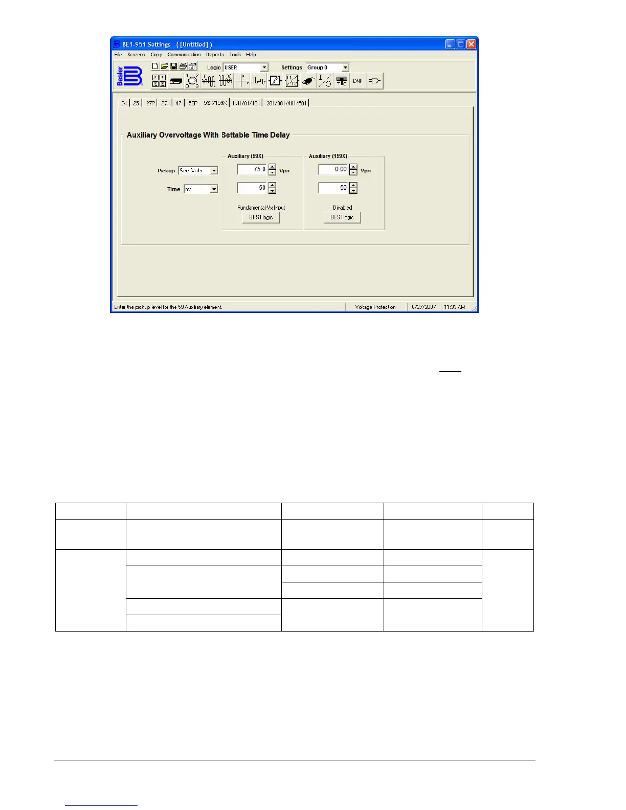
Figure 4-34. Voltage Protection Screen, 59X/159X Tab
At the top center of the screen is a pull-down menu labeled Logic. This menu allows viewing of the
BESTlogic settings for each preprogrammed logic scheme. A custom logic scheme must
be created and
selected in the Logic pull-down menu at the top of the screen before BESTlogic settings can be changed.
See Section 7, BESTlogic Programmable Logic. To the right of the Logic pull-down menu is a pull-down
menu labeled Settings. The settings menu is used to select the setting group that the elements settings
apply to.
Using the pull-down menus and buttons, make the application appropriate settings to the
Under/Overvoltage element.
Operating settings for Auxiliary Undervoltage/Overvoltage are summarized in
Table 4-25.
Table 4-25. Operating Settings for Auxiliary Undervoltage/Overvoltage
Setting Range Increment Unit of Measure Default
Pickup
0 = Disabled
1 to 150
0.1 for 0 to 99.9
1.0 for 100 to 150
Secondary Volts 0
50 to 999 milliseconds 1 Milliseconds
0.1 for 1.0 to 9.9 Seconds
1 to 600 seconds
1.0 for 10 to 600 Seconds
3 to 36,000 cycles (60 Hz)
Time Delay
2.5 to 30,000 cycles (50 Hz)
∗
Cycles
50 ms
∗ Time delays less than 10 cycles can be entered to the nearest 0.1 cycles from the front panel HMI. All
time delays can be entered to the nearest 0.01 cycles from the ASCII command interface. Time delays
entered in cycles are converted to milliseconds or seconds. Increment precision after conversion is limited
to that appropriate for each of those units of measure.
Example 1. Make the following changes to the 59X element. Refer to
Figure 4-34.
Pickup: 75 secondary volts
Time: 50 ms