6-30 BE1-951 Reporting and Alarm Functions 9328900990 Rev L
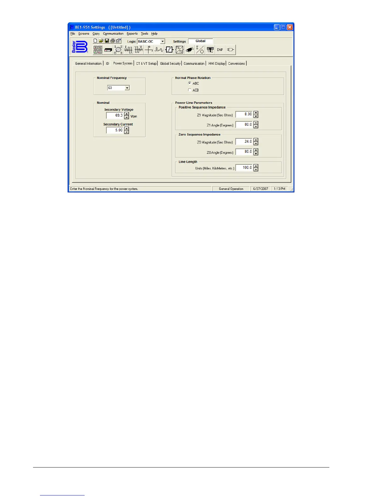
Figure 6-16. General Operation Screen, Power System Tab
SG-LINE Command
Purpose: Read/Set System Line parameters.
Syntax: SG-LINE=<Z1>,<A1>,<Z0>,<A0>,<LL>]
Comments: Z1, Z0 = impedance; A1, A0 = angle; LL = length
SG-LINE Command Example:
Example 1. Enter data for a power line with the following parameters:
Positive-sequence impedance: 0.47 ∠ 60° Ω/km
Zero-sequence impedance: 1.59 ∠ 70° Ω/km
Line length: 10 km
The data should be entered as the total impedance of the 10,000-meter power line.
Therefore, the data would be entered as:
>SG-LINE = 4.7,60,15.9,70,10
The BE1-951 calculates distance to fault each time a fault record is triggered. Refer to the fault record
triggering logic command SG-TRIGGER for triggering details. Distance to fault is calculated and displayed
based on the power line parameters. For more information on entering power line parameters, see
Section 3, Input and Output Functions.
Note that both Z1-MAG and Z0-MAG are scaled by 10 times to represent the entire length of the power
line. Since the units are in kilometers the distance results would also be in kilometers.
Distance calculations are preformed post-fault using vector data captured during the actual fault. Pre-fault
current vectors are captured three cycles prior to pickup. Fault voltage and current vectors are captured
two cycles after the trip command is issued. The two-cycle wait time allows line transients to settle to
provide more accurate results.
To perform the actual distance calculation, the BE1-951 first must determine the faulted phase. Faults
can be categorized depending on the lines faulted. The various categories are LLL, LL, LLG, or LG where
L = line and G = ground.
To determine the faulted phase, the fault vectors are compensated for load flow using the pre-fault data.
Next, the compensated vectors are run through a series of sequence component comparisons. Once the
faulted phase is determined, the fault data along with the line parameters are applied using the Takagi