9328900990 Rev L BE1-951 Human-Machine Interface 10-3
5. PROTECTION LOGIC – Provides display and setting of protective functions such as pickups and
time delays.
Figure 10-7 illustrates the structure of the Protection Logic menu branch.
6. GENERAL SETTINGS – Provides display and setting of relay configuration settings such as
communication, LCD contrast, transformer ratios, and system frequency. General Settings menu
branch structure is illustrated in
Figure 10-8.
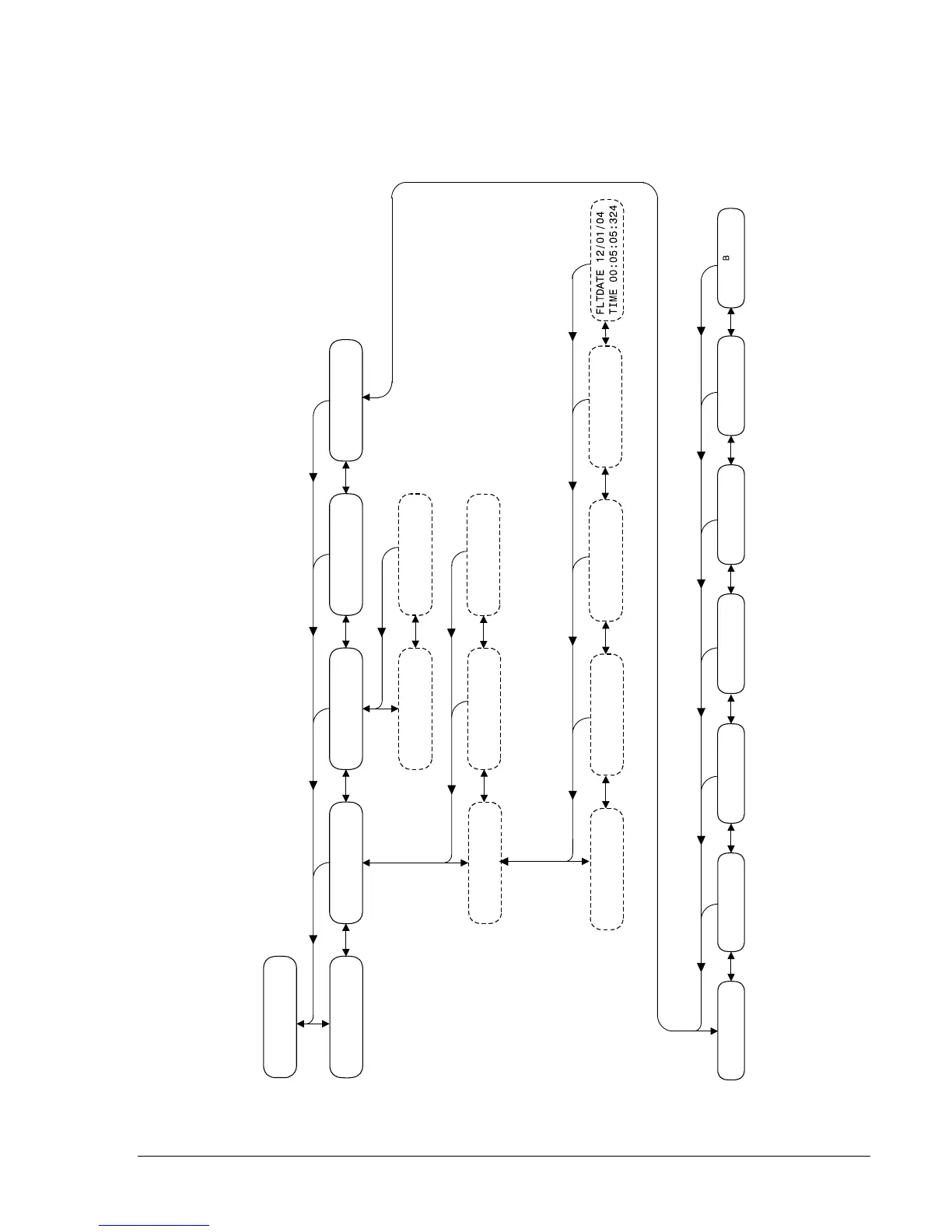
1 REPORT STATUS
1.1
RECLOSER
OFF
1.2
TARGETS
XXXX
1.3
ALARMS
XXXX
1.4
SCREEN
SCROLL
LIST
1.5
OPERATIONAL
STATUS
1.2.2
TARGETS
1.2.1
TARGETS
D2848-54
11-02-04
1.3.1 ALARMS 1.3.X ALARMS
1.5.1
IN
12345678
00000000
1.5.2 OUT A12345
000000
1.5.4 0123
CO-x43 0000
1.5.5
01
X86 STATUS 00
1.5.6 ACTIVE
GROUP 0
1.5.3 A12345
CO-OUT LLLLLL
150TABC, 150TN
51ABC, 51N
ETC.
IQ10.4K VX27.4K
FAULT IG10.4KA
VB27.4K VC27.4K
FAULT VA27.4K
IB10.4K IC10.4K
FAULT IA10.4K
25.0
FAULT DISTANCE
1.5.7 REAKER
CLOSED
Figure 10-3. Report Status Menu Branch