9328900990 Rev L BE1-951 Installation 12-21
Sidebar 12-1. Current Circuit Polarity
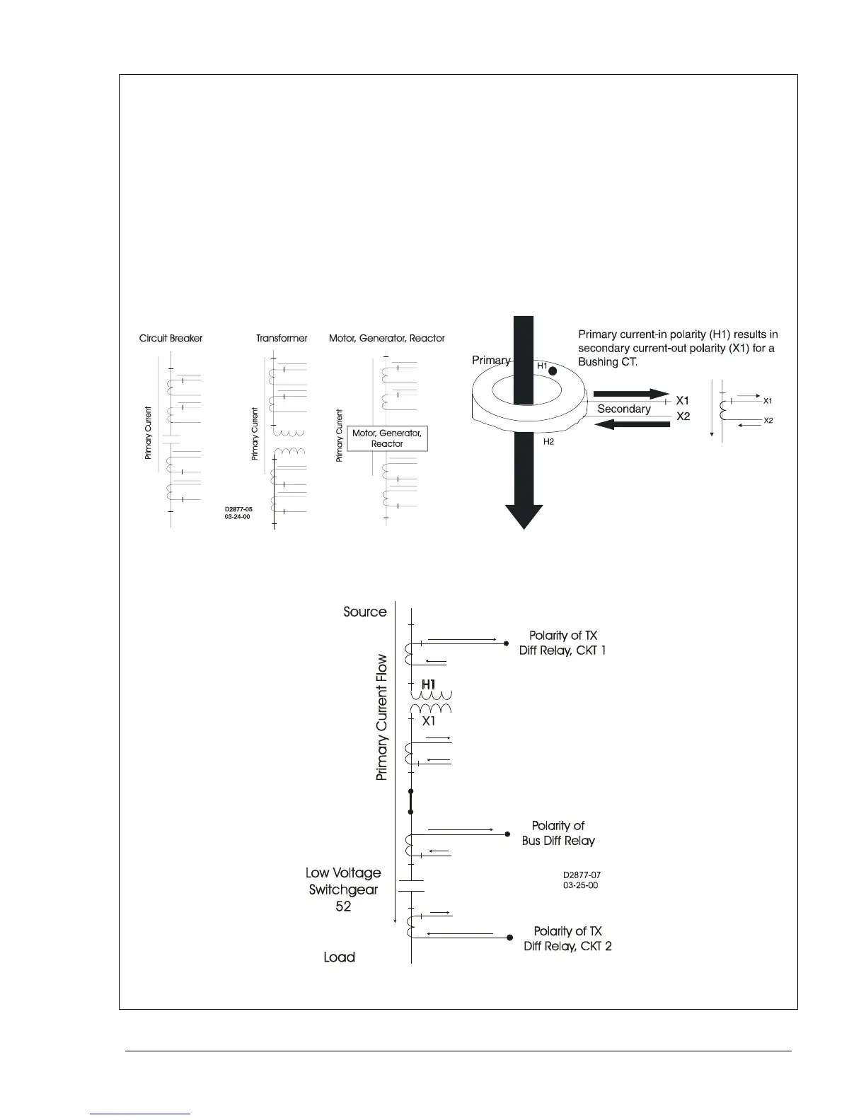
By ANSI convention, current transformer (CT) polarity will face away from the protected winding of a
transformer, motor, generator, or reactor, and away from the contacts in a circuit breaker. Therefore,
primary current flow towards the winding or contacts (direction of protected zone) will result in a
secondary current out X1, in phase with the primary (see Figures 12-20 and 12-21).
On occasion, however, protection engineers will run into situations where CT polarity is reversed for a
specific application. That is, non-polarity of the CT secondary will be in phase with the primary current
flow (Figure 12-22). For example, a transformer differential CT from a breaker with a different polarity
convention such as low voltage switchgear, or a bus differential CT taken from the low side of a
transformer.
Orientation of CT polarity relative to primary current flow establishes the secondary CT terminal that
should be connected to polarity of the protective relay.
D2877-06
07-17-00
Figure 12-20. Standard CT Polarity Figure 12-21. Current Transformer Action
Figure 12-22. Example of Reversed CT Polarity