9328900990 Rev L BE1-951 Installation 12-37
5
2
3
MATING CONNECTOR
FEMALE DB-9, DC
10-29-04
D2881-22
RFL 9660 REAR
PORT
TO BE1-951
1
2
3
4
5
TX
D
RXD
N.C
.
SGN
9
6
7
8
N.C
.
.
.
.
N.C
.
N.C
.
N.C
.
N.C
.
Figure 12-40. RFL 9600 Protective Relay Switch to BE1-951 Cable
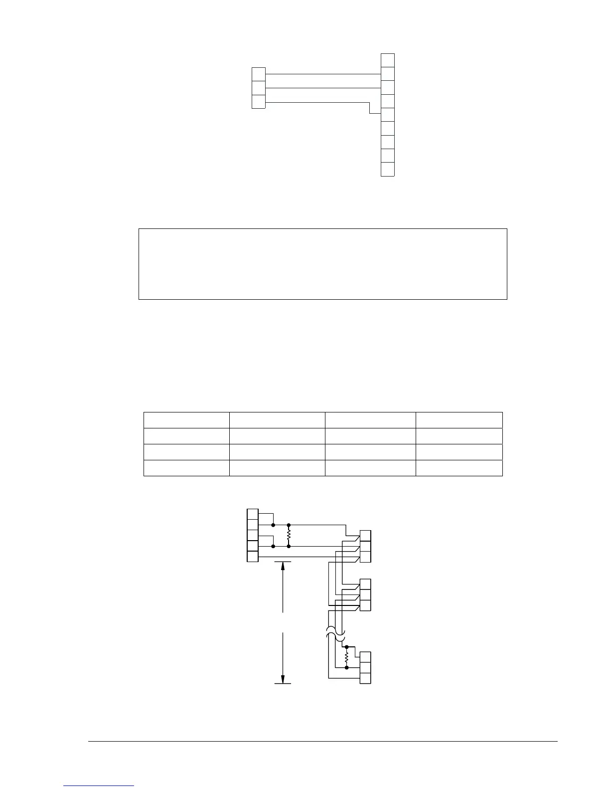
RS-485 Connectors
RS-485 connections are made at a three-position terminal block connector that mates with a standard
communication cable. A twisted pair cable is recommended. Connector pin numbers, functions, names,
and signal directions are shown in
Table 12-3. An RS-485 connection diagram is provided in Figure 12-
41.
Table 12-3. RS-485 Pinouts (COM 2)
Terminal Function Name Direction
A Send/Receive A (SDA/RDA) In/Out
B Send/Receive B (SDB/RDB) In/Out
C Signal Ground (GND) N/A
D2848-05
03-18-99
22
6
4
A
B
C
TO BE1-951
3 POSITION
TERMINAL BLOCK
DB-37 FEMALE
TO RS422/RS485
19
24
C
B
A
A
B
C
4000'
MAX.
COM 2
BE1-951
BE1-951
COM 2
BE1-951
COM 2
R
t
t
R
R = OPTIONAL TERMINATING
t
RESISTOR (120 S TYPICAL)
A
5
D5
D4
D3
D5
D4
D3
D5
D4
D3
Figure 12-41. RS-485 DB-37 to BE1-951
NOTE
The RS-232 communication ports are not equipped with Request to Send (RTS)
and Clear to Send (CTS) control lines. This makes the BE1-951 incompatible
with systems that require hardware handshaking or systems that use self-
powered RS-232 to RS-485 converters connected to the RS-232 ports.