9328900990 Rev L BE1-951 Testing and Maintenance 13-25
Table 13-24. 51P/51N/51Q Pickup Settings
Sensing Type Phase Commands Neutral Commands
Negative-Sequence
Commands
1 A S0-51P=0.1,0.5,I2,N S0-51N=0.1,0.5,I2,N S0-51Q=0.1,0.5,I2,N
5 A S0-51P=0.5,0.5,I2,N S0-51N=0.5,0.5,I2,N S0-51Q=0.5,0.5,I2,N
Step 3: Connect a current source to relay Terminals D1 and D2 (A-phase). Using the values listed in
Table 13-25 (table value x3 for 51Q), apply the appropriate current values and measure the
time between the application of current and the closure of OUT1, OUT2, and OUT3. Verify that
the relay performs within the specified limits.
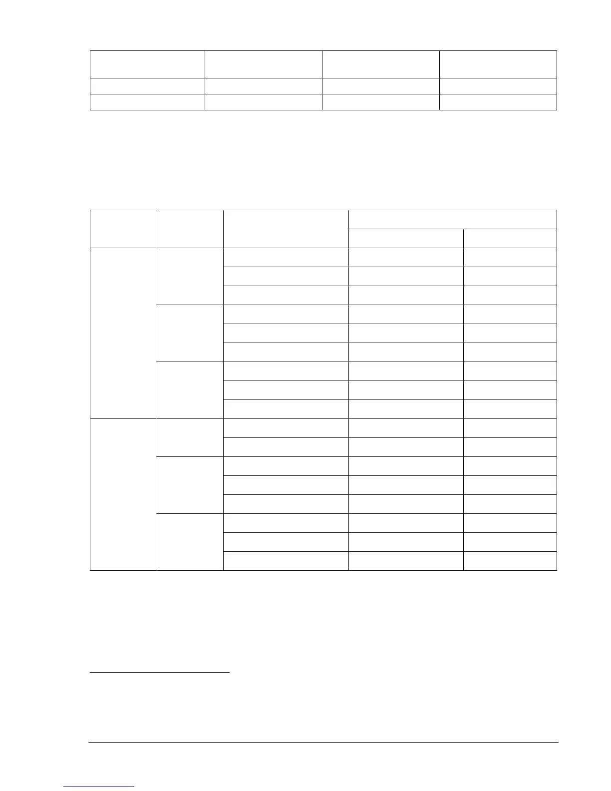
Table 13-25. 51P/51N/51Q Timing Values
Relay Trip Limits
Sensing
Type
Time Dial Applied Current
Lower Limit Upper Limit
0.15 A 0.748 sec 0.827 sec
0.50 A 0.190 sec 0.240 sec
0.5
2.5 A 0.100 sec 0.150 sec
0.15 A 7.244 sec 8.007 sec
0.50 A 1.798 sec 1.988 sec
5
2.5 A 0.944 sec 1.044 sec
0.15 A 14.318 sec 15.825 sec
0.50 A 3.535 sec 3.907 sec
1 A
9.9
2.5 A 1.844 sec 2.038 sec
2.5 A 0.190 sec 0.240 sec
0.5
12.5 A 0.100 sec 0.150 sec
0.75 A 7.244 sec 8.007 sec
2.5 A 1.798 sec 1.988 sec
5
12.5 A 0.944 sec 1.044 sec
0.75 A 14.318 sec 15.825 sec
2.5 A 3.535 sec 3.907 sec
5 A
9.9
12.5 A 1.844 sec 2.038 sec
Step 4: Repeat Steps 2 and 3 for all of the current and time dial settings for your current sensing type.
Step 5: (Optional.) Repeat Steps 2 through 4 for phase B (Terminals D3 and D4) and phase C
(Terminals D5 and D6).
Step 6: (Optional.) Using ASCII commands, substitute 151 for any 51 logic or setting command in each
test.
Pickup and Dropout Verification
Purpose: To verify the pickup accuracy of the 51P, 51N, 151N and 51Q elements.
Reference Commands: SL-51P, SL-51N, SL-51Q, SL-151N, SL-GROUP, SL-VO
Step 1: Connect a current source to Terminals D1 and D2 (A-phase). Refer to
Figure 13-1 for terminal
locations. An ohmmeter or continuity tester may be used to monitor output contact status.