9328900990 Rev L BE1-951 Testing and Maintenance 13-37
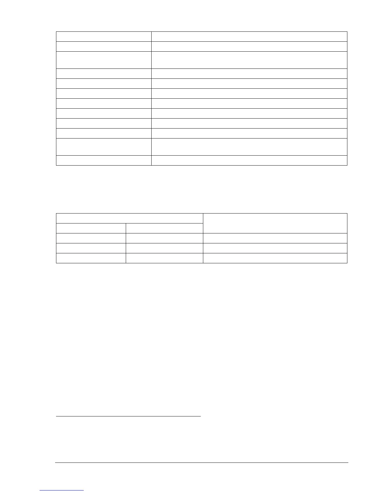
Table 13-49. 27P and 59P Pickup Test Commands
Command Purpose
A= Gains write access.
SL-N=NONE
Zero out custom logic settings. Overwrite with LOGIC=NONE
settings.
Y Confirm overwrite.
SL-N=27_59 Sets 27_59 as custom logic name.
SG-VTP=1,4W,PN,PN Set VT phase voltage parameters.
SA-MAJ=0 Disables Major Alarm.
SL-27P=1,0 Enables 27P, disables blocking.
SL-59P=1,0 Enables 59P, disables blocking.
SL-VO1=27PT+59PT Enables OUT1 to close for 27P or 59P trip.
SG-TRIG=27PT+59PT,
27PPU+59PPU,0
Enables 27P and 59P to log and trigger fault record.
EXIT;Y Exit and save settings.
Step 2: Using
Table 13-50 as a guide, transmit the first row of setting commands (highest 27P PU,
lowest 59P PU) to the relay.
Table 13-50. 27P and 59P Pickup Settings
Phase Pickup Settings
Undervoltage Overvoltage
Purpose
S0-27P=96,50ms S0-59P=132,50ms Sets 27P PU at 96 V, 59P at 132 V, TD at min
S0-27P=84,50ms S0-59P=144,50ms Sets 27P PU at 84 V, 59P at 144 V, TD at min
S0-27P=72,50ms S0-59P=156,50ms Sets 27P PU at 72 V, 59P at 156 V, TD at min
Step 3: Prepare to monitor the 27P and 59P function operation. Operation can be verified by monitoring
OUT1.
Step 4: Connect and apply a 120 Vac, three-phase voltage source to Terminals C13 (A-phase), C14 (B-
phase), C15 (C-phase), and C16 (Neutral). Refer to
Figure 13-1 for terminal locations.
Step 5: Slowly decrease the A-phase voltage until OUT1 closes. Pickup should occur within ±2 percent
or 1 volt of the 27P pickup setting. Slowly increase the A-phase voltage until OUT1 opens.
Dropout should occur between 102 and 103 percent of the actual pickup value. Verify the 27A
target and the HMI. Reset the target.
Step 6: Continue increasing the A-phase voltage until OUT1 closes. Pickup should occur within ±2
percent or 1 volt of the 59P pickup setting. Slowly reduce the A-phase voltage until OUT1
opens. Dropout should occur between 97 and 98 percent of the actual pickup value. Verify 59A
target on the HMI.
Step 7: Verify the pickup and dropout accuracy of the middle and upper pickup settings listed in
Table
13-50.
Step 8: (Optional.) Repeat Steps 2 through 7 for the B-phase and C-phase voltage inputs.
Step 9: (Optional.) Repeat Steps 2 through 8 for Setting Groups 1, 2, and 3.
Phase Undervoltage/Overvoltage Timing Verification
Step 1: Using
Table 13-51 as a guide, transmit the first row of setting commands to the relay.