9328900990 Rev L BE1-951 BESTCOMS Software 14-15
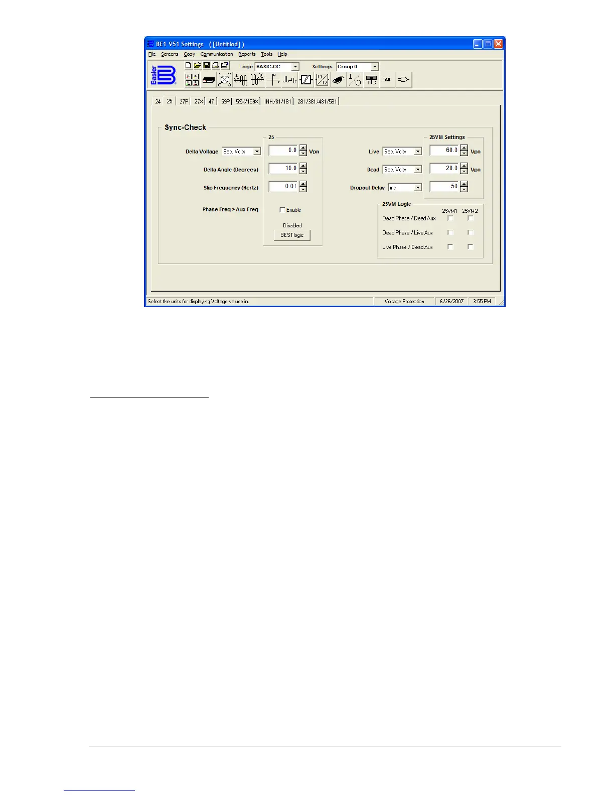
Figure 14-18. Voltage Protection Screen, 25 (Sync-Check) Tab
Set the 25 VM - Live and Dead threshold levels. Set the Dropout Delay (time delay between sensing
dropout and clearing VM1 logic bit) unit of measure and value. Select the 25VM Logic that will set the
VM1 and VM2 logic bits.
27P (Phase Undervoltage)
This tab (
Figure 14-19) allows you to configure the phase undervoltage with settable time delay elements.
The pull down Pickup menu allows you to select the relative pickup quantity within a range of 10.0 to 300
volts. The BE1-951 relay measures the voltage input in secondary voltage (default). If you want to use
primary volts, per unit volts, or percent volts, you must coordinate the settings in CT & VT Setup and
Conversions. Whatever the measurement, the method is displayed beside the settings - e.g., V
PP
(voltage, phase-to-phase). Select the Time delay unit of measure and the value for the 27P element in the
range of 50 to 600,000 milliseconds. Select the BESTlogic box at the bottom of the Phase (27P) column.
The status of the logic is shown above the BESTlogic box. A dialog box (BESTlogic Function Element)
opens showing the status of the element logic and the logic scheme name. If you have a custom logic
scheme active, you may change the status of the element logic by pulling down the menu and selecting
from the available choices.