9328900990 Rev L BE1-951 Protection and Control 4-25
Table 4-12 summarizes the polarization settings for Directional Overcurrent. In the table, Q represents
negative-sequence polarization, V represents zero-sequence polarization, and I represents current
polarization.
Table 4-12. Polarization Settings for Directional Overcurrent
Setting Range/Purpose Default
QVI = Use all three polarization methods for neutral elements.
QV = Use negative and zero-sequence polarization for neutral elements.
QI
= Use negative-sequence and current polarization for neutral
elements.
VI = Use zero-sequence and current polarization for neutral elements.
Q = Use negative-sequence polarization for neutral elements.
V = Use zero-sequence polarization for neutral elements.
Mode
I = Use current polarization for neutral elements.
QVI
VOIN
= Calculated zero-sequence voltage is compared to calculated zero-
sequence current.
VOIG
= Calculated zero-sequence voltage is compared to measured ground
current on the independent ground CT input.
VXIN
= Measured 3V0 voltage on the auxiliary voltage input (VX) is
compared to calculated zero-sequence current.
Zero-
Sequence
Voltage
Polarization
Quantities
VXIG
= Measured 3V0 voltage on the auxiliary voltage input (VX) is
compared to the measured ground current on the ground CT input
(IG).
VOIN
Modes QVI, QV, QI, and VI are logical OR’s of modes Q, V, and I and are used to setup dual or possibly
triple polarization techniques for the neutral elements. Thus, if more than one directional supervision
element is enabled, any one can enable tripping if the appropriate forward or reverse directional decision
is made.
The directional algorithm requires the power line impedance parameters. These parameters are input into
the BE1-951 using BESTCOMS, the SG-LINE ASCII command or HMI Screens 6.3.10 through 6.3.12.
Table 4-13 provides the power line impedance settings.
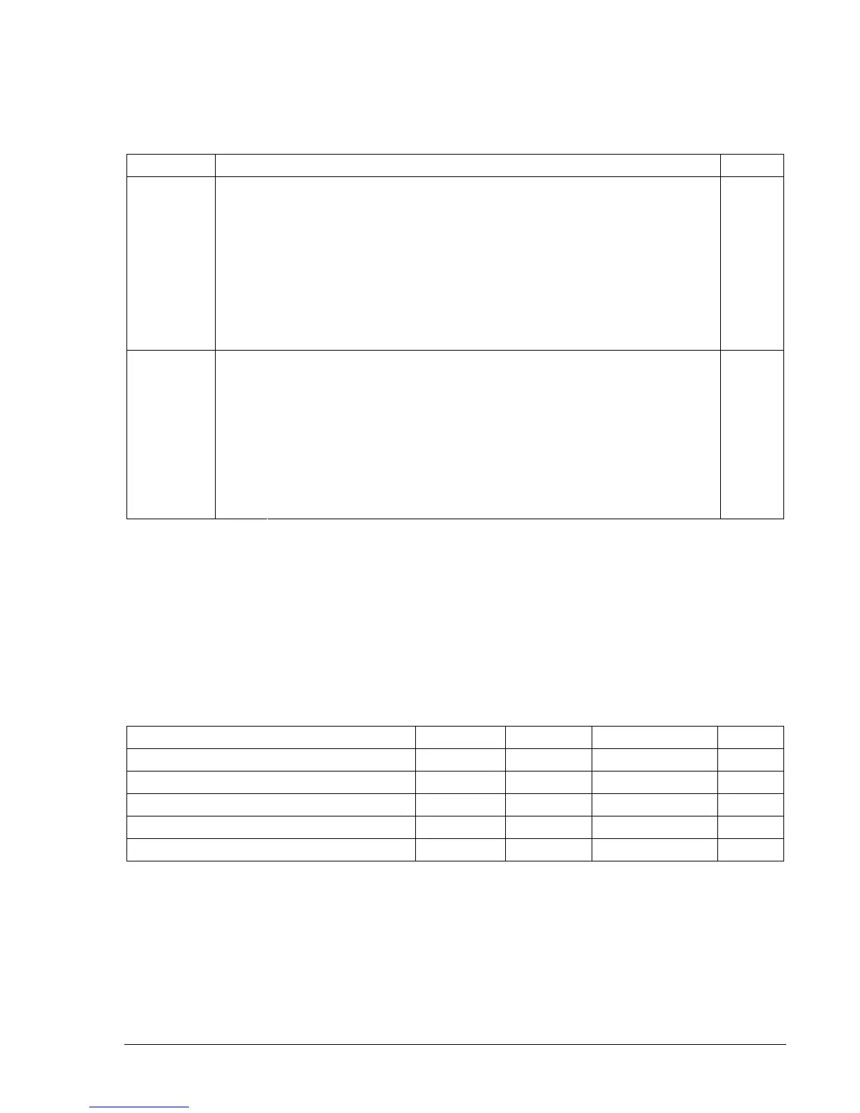
Table 4-13. Power Line Impedance Settings
Setting Range Increment Unit of Measure Default
Positive-Sequence Magnitude (Z1) 0.05 to 200 0.05 Ohms 8
Positive-Sequence Impedance Angle (A1) 0 to 90 1 Degrees 80
Zero-Sequence Magnitude (Z0) 0.05 to 650 0.05 Ohms 24
Zero-Sequence Impedance Angle (A0) 0 to 90 1 Degrees 80
Length of Power Line (LL) 0.01 to 650 0.01 Units 100
Only the angle parameters are used in determining the fault direction. The other parameters are used for
fault location as described in Section 6, Reporting and Alarm Functions, Fault Reporting. An entry for Z2
negative-sequence impedance is not required since Z2 and Z1 are considered to be equal. These angles
represent the line angle present between the sequence voltage and current if a fault has occurred on the
power line.
A fault current is considered to be in a forward direction when the current, after being offset by the line
angle, is in phase with the voltage. The forward direction zone extends for approximately ±90° from the
nominal line angle. A similar argument applies for the reverse direction with the current 180° out of phase
from the voltage. Z1’s angle is used during positive and negative-sequence directional test. Likewise, Z0’s