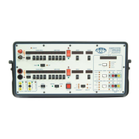
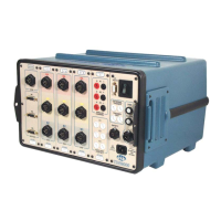
TDR9000
™
Circuit Breaker Test System User’s Guide
72A-1898 Rev. A 11/01 B-29
Monday, November 26, 2001 1:09 pm
WARNING All the cables used for this test should be detached from the breaker
while performing this procedure.
Example
Connect a Trip clip to a contact clamp, connect a Close clip to
another contact clamp, and connect the remaining Trip/Close clips to
the common clamp.
2. Run a test sequence that exercises both controls (e.g., Trip Free,
Reclose, O-C-O).
3. Check for activity on both contact channels.
• If only one control is misbehaving, the test can be done using
only one contact channel and the suspect T/C clip pair. Run a
simple test (e.g., Trip, Close).
• If both the Trip and Close control pulses are seen on the contact
channels graphs, the TDR9000 is OK. The problem is outside the
Instrument.
• If one or both of the patterns is missing, check the fuses with a
meter.
• If the fuses are OK, then the cable is suspect.
• If the fuses and cables are OK, then replace the Trip/Close
module. Refer to ”Internal Circuit Boards” on page B-19.
• Otherwise, replace the bad fuse. Refer to ”Replacing
Trip/Close Fuses”.
Replacing
Trip/Close Fuses
To replace fuses:
1. Turn the power OFF.
2. Remove and replace the defective fuse using a flat head screwdriver.
WARNING Always use a bus type 3 A, 250V Slo-Blo (Doble Part # 384-0002). Use
of any fuse other than the designated type can result in damage to the
TDR9000.
3. Restore system connections.
4. Turn the power ON.


 To Next Page