Diagnostic instruments
file:///D|/Manuales/Para%20recolocar/MOTOS/DUCATI/DUCATI/M796/wsm/EN/M796_ABS_11_6_13.36.1.html[11/12/2015 18:40:27]
utilised to check the resistance value across several sensors. For example, after disconnecting the electrical wiring to the
rpm/ignition-injection system timing sensor (on the camshaft drive gear) the relative internal resistance can be checked
by connecting a multimeter to its terminals. This makes it possible to check the electrical continuity of the winding inside
the sensor (a reading of infinite resistance indicates that the winding is interrupted). Resistance measurement can also be
used to check the continuity of sections of the electrical circuit or relay type switches. For example, to check the condition
of a section of the electrical circuit between two connections, disconnect the connections and connect the terminals of the
multimeter to the ends of the electrical cable in question to check that the specified resistance value is present. If this
value is close to zero (i.e. lower than approximately 0.3 ohm) this means that the cable is not interrupted. Some
instruments feature an audible signal that is emitted when the resistance approaches a value of zero. The same procedure
must be adopted to check whether, for example, two contacts of a switch (relay or manual type) are making the contact
correctly when closed. In this case the terminals of the multimeter must be connected to the switch terminals, checking
that the resistance value is close to zero (or listening for the audible signal) when the switch is closed. To check that the
multimeter is functioning correctly in “electrical continuity test” mode, short out the two test probes. The resistance value
indicated must be almost nil and the audible signal must be activated.
Protections and precautions
The multimeter is equipped with protective fuses and batteries. These components must always be in perfect condition to
ensure that the instrument is functioning correctly. When making electrical measurements always use the maximum
caution to avoid short circuits, which can otherwise cause irreparable damage to the electric system and constitute a
personal injury hazard. All maintenance work must be performed exclusively when the system is not live (disconnect the
battery in advance). NEVER connect the multimeter in parallel to make current measurements, and NEVER connect it in
series to carry out voltage measurements.
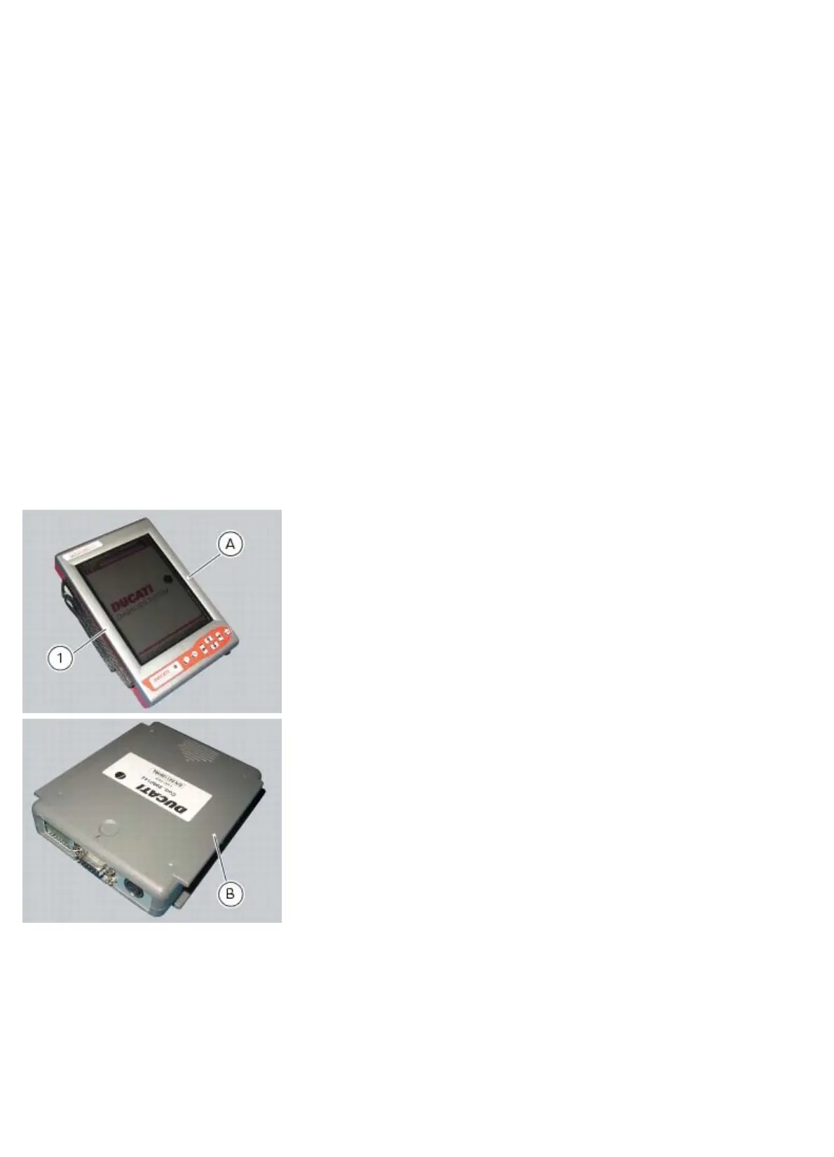
Description of the Ducati Diagnostic System tester
The “DDS” diagnostic system lets you diagnose any faults in the injection-ignition system via a serial port. The system is
also equipped with functions to test various devices on the motorcycle. The DDS diagnosis instrument can be used to
measure current and voltage on any electrical device, to perform tests on individual components and to measure pressure
and temperature values.
The DDS diagnosis instrument (1) tool code 97900.0215 comprises a palmtop display unit (A), a BBAD self-diagnosis
module (B) and a display memory card (C).