Cylinder head assemblies: checks and adjustments
file:///D|/Manuales/Para%20recolocar/MOTOS/DUCATI/DUCATI/M796/wsm/EN/M796_ABS_11_9_4A.67.1.html[11/12/2015 18:40:44]
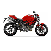
Checking valve lift
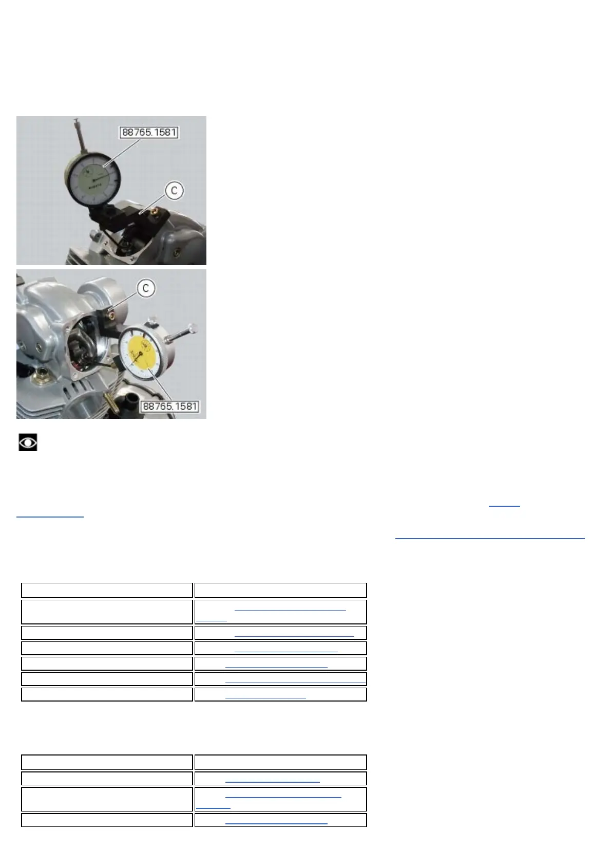
Fit the gauge (C) 88765.1581 in correspondence with the fixing hole of the previously removed head valve cover,
as shown in the figure.
Reset the valve opening clearance when the camshaft is in its rest position by inserting the blade of a feeler gauge
between the upper rocker arm and the opening shim.
Note
This operation is best done using one dial gauge for the exhaust valve and another one for the intake valve.
Make sure the dial gauge fork is centred relative to the valve axis and located against the closing shim.
Set the dial gauge to zero when the valve is fully closed.
Rotate the intake camshaft so as to allow the intake valves to lift fully.
Check on the dial gauge that the measured value corresponds to the prescribed one (Sect. 3 - 1.1,
Timing
system/valves).
Perform the same procedure for the exhaust valve, fixing the support to the opposite side of the cylinder head.
Refit the components by carrying out the same Operations indicated in chapter “
Checking and adjusting valve clearances”,
previously described.
Remove the tools 88765.1581.
Operations Section reference
Refit the timing belt covers 9 - 4.2,
Refitting the timing belt
covers
Refit the valve covers 9 - 4.3,
Refitting the valve covers
Refit the oil cooler to the frame 9 - 2.2,
Refitting the oil cooler
Refit the fuel tank 8 - 2,
Refitting the fuel tank
Refit the tank covers 5 - 2,
Refitting the fuel tank fairings
Refit the seat 5 - 3,
Refitting the seat
Checking the engine timing
Operations Section reference
Remove the seat 5 - 3, Removal of the seat
Remove the tank covers 5 - 2,
Removal of the fuel tank
fairings
Remove the fuel tank 8 - 2,
Refitting the fuel tank