Crankcase assembly: crankshaft/connecting rods assembly
file:///D|/Manuales/Para%20recolocar/MOTOS/DUCATI/DUCATI/M796/wsm/EN/M796_ABS_11_9_9C.80.1.html[11/12/2015 18:40:54]
Remove the oil pump 9 - 2.1, Removal of the oil pump
Remove the primary gear 9 - 6.3,
Removal of the primary
drive gear
Remove the alternator-side
crankcase cover
9 - 8,
Removal of the generator
cover
Remove the flywheel/alternator
assembly
9 - 8,
Removal of the
flywheel/alternator assembly
Remove the starter motor idler
gear
9 - 9.1,
Removal of the starter
motor idler gear
Remove the starter motor 6 - 3,
Removal of the starter motor
Remove the side timing belt covers 9 - 4.2,
Removal of the timing belt
covers
Remove the timing belts 9 - 4.2,
Removal of the timing
system assembly
Remove the complete cylinder head
unit
9 - 4.4,
Removal of the cylinder
head assembly
Remove the cylinder barrel/piston
assemblies
9 - 5,
Removal of the
cylinder/piston assembly
Remove the mesh filter 4 - 3,
Changing the engine oil and
filter cartridge
Separate the crankcase halves 9 - 9.2,
Separation of the
crankcase halves
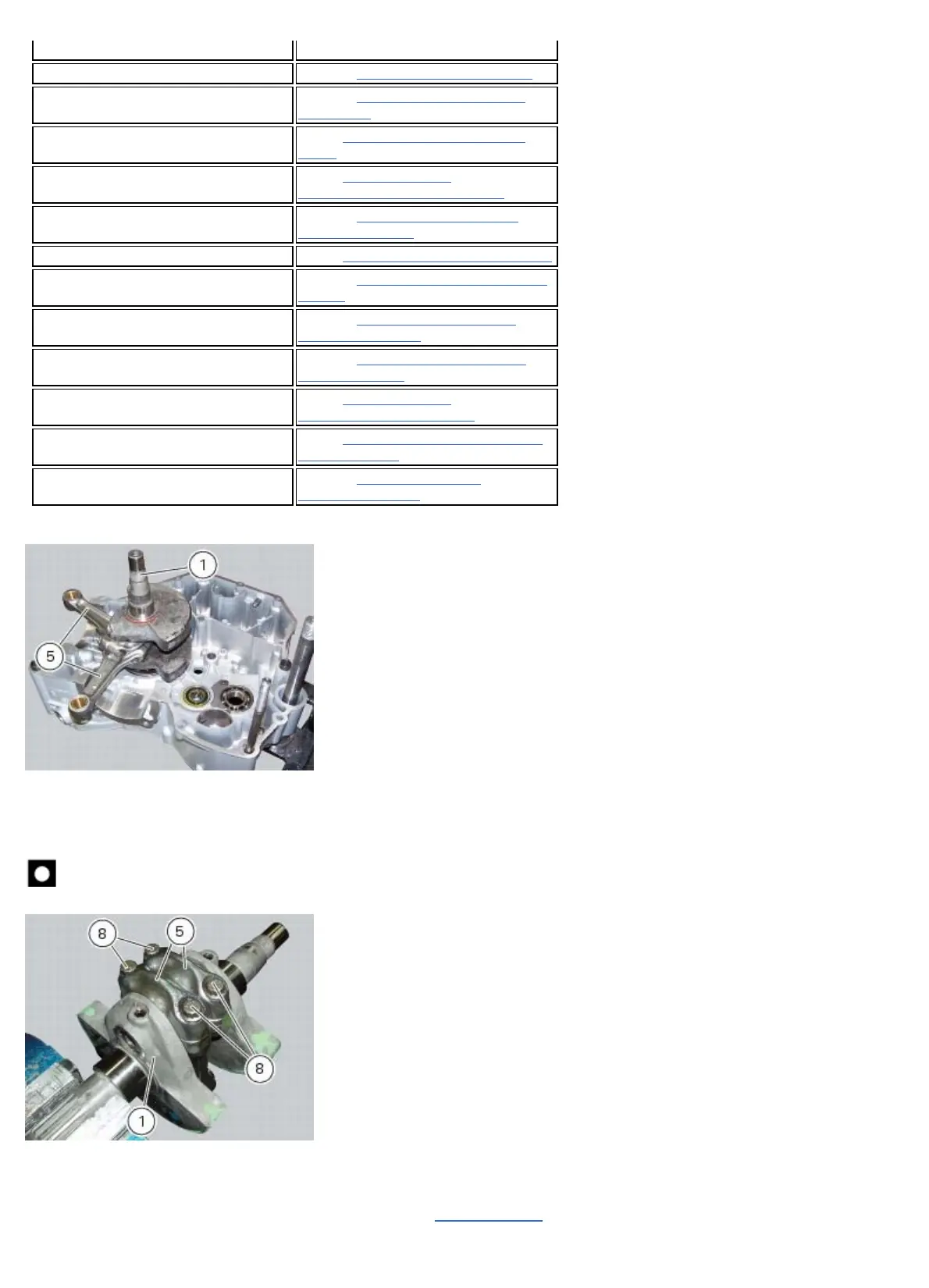
After separating the crankcase halves, withdraw the crankshaft (1) complete with connecting rods (5).
Disassembly of the crankshaft/connecting rods assembly
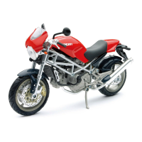
Unscrew the screws (8) and separate the connecting rods (5) from the crankshaft (1).
Important
Take care not to mix up components of different connecting rods and maintain the original orientation.
Overhaul of the connecting rods
Make the following dimensional checks on the connecting rods:
-clearance with gudgeon pin on assembly (Sect. 3 - 1.1,
Cylinder/Piston).
In the event of excessive wear, replace the connecting rod. The small end bushing must be in good condition and firmly
driven into its seat. Check for parallelism error measured at 100 mm from the connecting rod longitudinal axis:









 To Next Page