ABS system information
file:///D|/Manuales/Para%20recolocar/MOTOS/DUCATI/DUCATI/M796/wsm/EN/M796_ABS_11_7_5.42.1.html[11/12/2015 18:40:31]
5 - ABS system information
Operating principle
The Ducati ABS brake system manages the front and rear brakes separately. A pulse generator (phonic wheel), with a
ring of slots, is fixed onto each wheel. On the left calliper mounting bracket of the front fork and on the rear brake calliper
holder plate are HALL effect sensors which detect the full sections and voids on the phonic wheel as the vehicle moves,
providing and instantaneous wheel speed reading. These sensors transmit the data to the ABS control unit, which contains
software implementing a specific control algorithm developed by Ducati. The software compares the average speed of the
vehicle against the instantaneous wheel speed values to determine the degree of skidding. If the pressure applied to the
calliper by the rider causes the control limits to be exceeded, the control unit intervenes in the braking circuit relative to
the wheel for which incipient lock-up is detected. The ABS modulates the calliper pressure with a system of solenoid
valves that initially prevents any further increase in hydraulic pressure (EV valve closed), and then reduces pressure (AV
valve opened). The AV valve is opened in a series of pulses (with less than 10 milliseconds between successive pulses), to
reduce pressure in steps. When the wheel begins to rotate again in response to the diminished braking force applied and
the wheel speed reaches the reference value, the AV release valve is closed.
Simultaneously, the EV inlet valve is reopened, restoring normal operation of the brake system. The ABS control unit can
monitor and modulate brake force accordingly in the three following different conditions: dry road surface (high grip), wet
or greasy road surface (poor grip) and uneven road surface. ABS functionality is disabled at vehicle speeds lower than
5 km/h.
A diagram illustrating how the ABS system functions is given below.
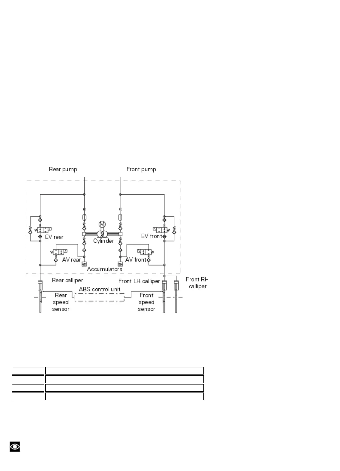
The hydraulic component of the ABS system consists of a primary circuit (from the cylinder to the control unit and from
the control unit to the calliper) and a secondary circuit (completely within the control unit). The hydraulic layout of the
ABS system is given below.
Key for ABS hydraulic system layout
EV rear Rear calliper inlet valve
AV rear Rear calliper outlet valve
EV front Front calliper inlet valve
AV front Front calliper outlet valve
ABS system operating information
The response of the system is based on the analysis of the speed signals for front and rear wheels; the system is
automatically deactivated if either of these signals is missing.
Note
In the event of the ABS control unit detecting a fault in the ABS electronic management system, it activates the specific