Cylinder head assemblies: checks and adjustments
file:///D|/Manuales/Para%20recolocar/MOTOS/DUCATI/DUCATI/M796/wsm/EN/M796_ABS_11_9_4A.67.1.html[11/12/2015 18:40:44]
Remove the oil cooler from the
frame
9 - 2.2, Removal of the oil cooler
Remove the valve covers 9 - 4.3, Removal of the valve
covers
Remove the timing belt covers 9 - 4.2,
Removal of the timing belt
covers
Note
For clarity, the figures show the engine block removed from the frame.
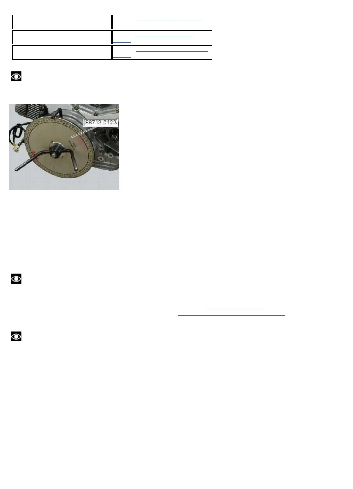
Remove the inspection cover (A) and install service tool no. 88713.0123.
Turn crankshaft with tool no. 88713.0123, and set it so that the horizontal piston is at the TDC in the combustion stage,
i.e. the valves of the horizontal head are all at rest position: check the valve clearance on the horizontal cylinder head.
Set the degree wheel of service tool no. 88713.0123: to zero the horizontal cylinder is at top dead centre of the
expansion stroke, and therefore we can proceed to check the valve clearances on this cylinder.
To measure valve clearances in the vertical cylinder, rotate the crankshaft counterclockwise through 270° from this
position. This will bring the vertical cylinder to top dead centre of the expansion stroke, and therefore we can proceed to
check the valve clearances on this cylinder.
Checking the opening clearance (Sa) of the intake/exhaust valves
To check the valve opening clearance (Sa), insert the blade of a feeler gauge between the opening rocker (C) and the
shim (3).
Note
While inserting the blade of the feeler gauge to check the clearance, apply gentle leverage to overcome the force of the
closing rocker spring and thus eliminate any play in the rocker mechanism: then check that the shim can rotate freely.
The clearance values must be within the specified limits (Sect. 3 - 1.1,
Timing system/valves).
If not, remove the opening shim (3), as described in chapter “
Removal of the cylinder head assembly”, Sect. 9 - 4.4, and
replace it with one of suitable height to obtain the prescribed assembly clearance.
Note
Opening rocker arm shims measuring 1.8 to 3.45 are available as spare parts: the size is punched on the shim.













 To Next Page