Operating manual.
CNC 8060
CNC 8065
PLC
20.
"Logic analyzer" service
·367·
(REF: 1807)
20.9.1 Editing logic analyzer data
In order to capture trace data, the user must enter the variables or expressions to be
analyzed, the trigger type and conditions as well as the time based to be used to display the
captured values. To edit this data, select the graphic area of the logic analyzer and press
the "Edit view" softkey to place the cursor on the data editing area.
Definition of variables
Up to 8 PLC variables or expressions may be defined to obtain their trace. The definition of
the expression cannot exceed 80 characters.
When modifying a variable, if there was already a trace of that expression, the trace will be
deleted when validating the new edition.
Trigger condition
A trigger condition is the one used to capture data and may be defined with a PLC variable
or expression. The definition of the expression cannot exceed 80 characters.
If the trigger condition is modified after a data capture, all the traces will be deleted when
validating the new condition.
Trigger type
It sets whether the data is to be captured "before", "after" or "before and after" the selected
trigger condition is met.
Time base
The operator may use this parameter to assign the timeframe to each vertical division. The
size of these divisions, therefore the resolution of these signals will be determined by this
time base. Consequently, the smaller the time base, the greater the signal resolution.
The value is given in milliseconds or microseconds according to the active units and the
selected value will be displayed in the information area.
Key. Meaning.
Move the cursor through the data.
Move the cursor within a data.
Open/close pop-up menus.
Validate the defined data.
Cancel edit.
By default The data capture starts and ends when the operator selects the option to execute
and stop the trace.
Before The data capture starts when the trigger condition is met and ends when the
operator selects the option to stop the trace.
Once the trace has been executed, the trigger signal will be shown at the beginning
of the trace.
After The data capture starts when the operator selects the option to execute the trace
and ends when the trigger condition is met.
Once the trace has been executed, the trigger signal will appear at the end of the
trace.
In the middle The data capture starts and ends when the operator selects the option to execute
and stop the trace.
Once the trace has been executed, the trigger signal will be shown at the center
of the trace.
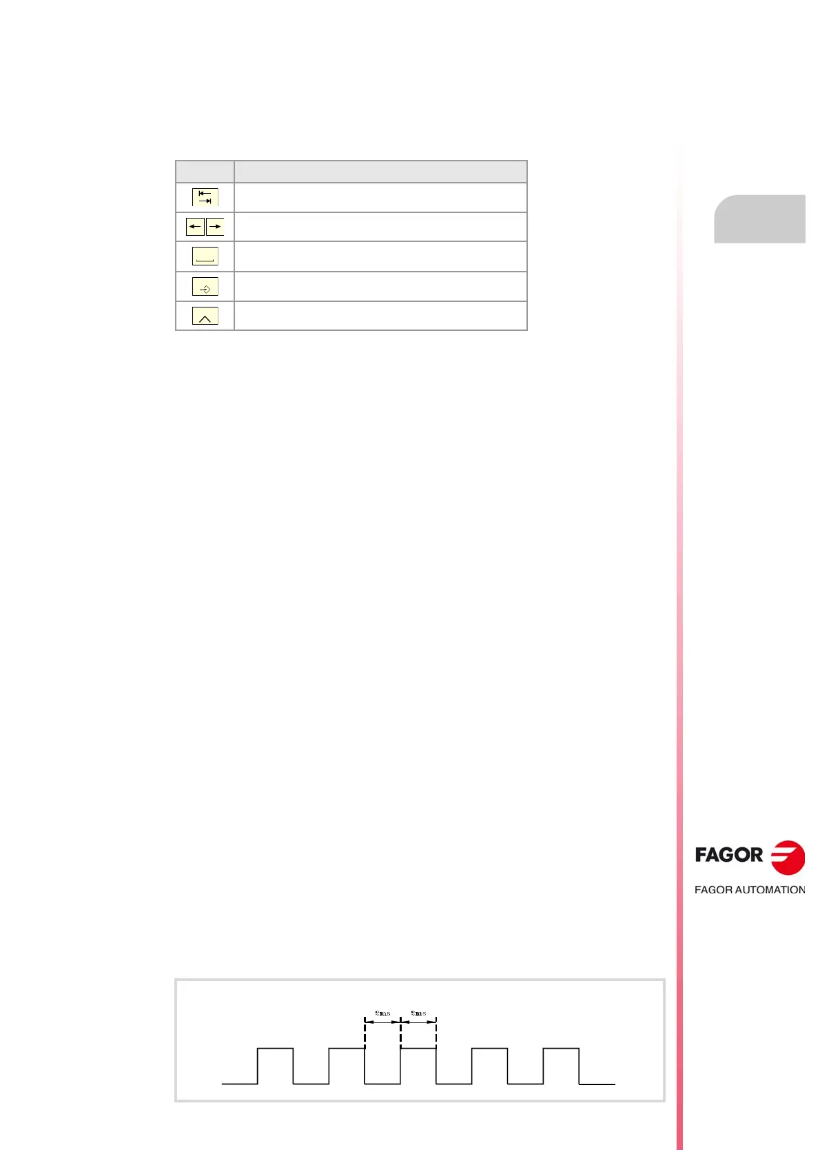
There is a mark that changes states every 2ms.