Operating manual.
CNC 8060
CNC 8065
KINEMATICS CALIBRATION.
26.
Kinematics calibration (Kinematic offsets).
·477·
(REF: 1807)
26.1.4 How to calibrate a kinematics.
To calibrate the kinematics, the user must first define a series of data, such as the dimensions
of the calibration ball, the amplitude of the movements of the rotary axes, etc. The CNC then
makes the necessary movements to calibrate the kinematics. Once the movements are
completed, the CNC shows the data obtained and it suggests new values for the kinematcis.
It is up to the user to update the corresponding machine parameters.
How to calibrate a kinematics.
1 Calibrate the probe and measure its length up to the tip with the same measuring system
used for measuring the tools.
2 Activate the kinematics to be calibrated.
3 Go into jog mode. Place the axes of the kinematics in their resting position. Place the
probe about 10 mm (0.4 inch) over the ball.
4 Access the kinematics calibration mode. This mode is only available from the task
window ([CTRL][A]).
5 When accessing this kinematics calibration mode, the CNC shows the data setting page.
See
"26.1.1 Page 1. Data editing page." on page 473.
On this page the data must be defined that is required for calibration, as well as the
dimensions of the ball, the path of the rotary axes, the probe movement, etc. The
horizontal softkey menu allows the axes to be selected for calibration; it is recommended
to calibrate all the axes of the kinematics.
6 Press the [START] key to start the calibration. The CNC switches to the page of the
captured data and starts the calibration. See
"26.1.2 Page 2. Page to display the
captured position values (coordinates)."
on page 475.
The CNC positions the rotary axes and carries out a measuring cycle. In each measuring
cycle, the CNC makes the necessary movements to touch the ball in 4 points (at 90º).
The CNC carries out several measuring cycles, it rotates the rotary axes for each of these
cycles according to what has been set on the data page (page 1).
7 When the data capture is completed, the CNC switches to the page of calculated data.
This page shows, for each TDATA parameter of the kinematics, the values and offsets
defined in the machine parameters and the new calculated values. On this page, it is
possible to select whether to update the OEM defined offset values on the machine
parameter table or to keep the original values. See
"26.1.3 Page 3. Page to display the
calculated data." on page 476.
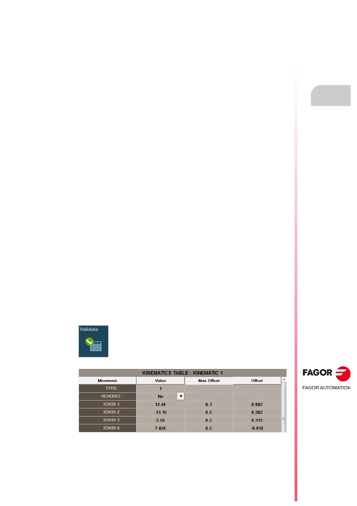
Updating the machine parameter tables.
Depending on the protection mode the CNC is in, it is possible to modify the
field “Value” (SETUP mode) or the field “Offset” (SETUP or USER mode) of
machine parameter table. To do this, select the data from the results page to
be modified and press the “Validate” softkey.
Machine parameter tables for the kinematics.