Garmin G2000 Pilot’s Guide for the Cessna T240
190-01263-01 Rev. A88
Flight instruments
sYstem
OVerVieW
Flight
instruments
eis
AuDiO PAnel
& Cns
Flight
mAnAgement
hAZArD
AVOiDAnCe
AFCs
ADDitiOnAl
FeAtures
APPenDiCesinDeX
PATHWAYS
Pathways provide a three-dimensional perspective view of the selected route of flight shown as colored
rectangular boxes representing the horizontal and vertical flight path of the active flight plan. The box
size represents 700 feet wide by 200 feet tall during enroute, oceanic, and terminal flight phases. During
an approach, the box width is 700 feet or one half full scale deviation on the HSI, whichever is less. The
height is 200 feet or one half full scale deviation on the VDI, whichever is less. The altitude at which the
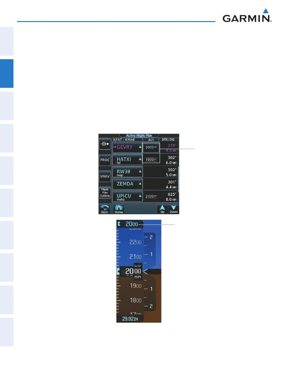
pathway boxes are displayed is determined by the higher of either the selected altitude or the VNAV altitude
programmed for the active leg in the flight plan (Figure 2-33).
The color of the rectangular boxes may be magenta, green, or white depending on the route of flight and
navigation source selected. The active GPS or GPS overlay flight plan leg is represented by magenta boxes
that correspond to the Magenta CDI. A localizer course is represented by green boxes that correspond to a
green CDI. An inactive leg of an active flight plan is represented by white boxes corresponding to a white line
drawn on the Inset map or MFD map indicating an inactive leg.
Figure 2-33 Selected and Programmed Selected Altitude
Selected
Altitude
Programmed
Altitudes
This manual downloaded from http://www.manualowl.com