Garmin G2000 Pilot’s Guide for the Cessna T240
190-01263-01 Rev. A34
SYSTEM OVERVIEW
SYSTEM
OVERVIEW
FLIGHT
INSTRUMENTS
EIS
AUDIO PANEL
& CNS
FLIGHT
MANAGEMENT
HAZARD
AVOIDANCE
AFCS
ADDITIONAL
FEATURES
APPENDICESINDEX
SYSTEM
OVERVIEW
FLIGHT
INSTRUMENTS
EIS AUDIO & CNS
FLIGHT
MANAGEMENT
HAZARD
AVOIDANCE
AFCS
ADDITIONAL
FEATURES
APPENDICESINDEX
1.4 SYSTEM OPERATION
The displays are connected via a single Ethernet bus for high-speed communication. As shown in Figure
1-1, each IAU is connected to a single display. This allows the units to share information, enabling true system
integration.
NORMAL DISPLAY OPERATION
In normal operations, PFD present graphical fl ight instrumentation (such as heading, airspeed, altitude,
vertical speed) on the Primary Flight Display (PFD) in either Full Mode or Split Mode. In Full Mode, the PFD
occupies the entire display portion of the GDU 1400W. In Split Mode, the PFD is condensed to accommodate
a Display Pane on the inboard portion of the GDU 1400W.
The MFD displays a navigation information, as well as fl ight plan, weather, traffi c and terrain information in
either two Half Mode Display Panes or one Full Mode Display Pane, depending on the selection made on the
Touchscreen Controller. The left portion of the MFD is dedicated to the Engine Indication System (EIS; see the
EIS Section).
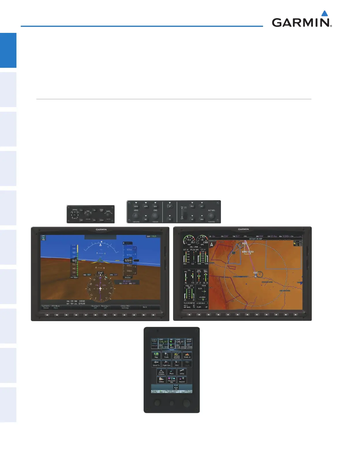
The Touchscreen Controller provides radio management, Display Pane control, data entry, as well as feature
selection and display of system information.
Figure 1-26 G2000 Normal Operation
This manual downloaded from http://www.manualowl.com