GE HEALTHCARE
DIRECTION 5394141, REVISION 5 LOGIQ™ P5 SEVICE MANUAL
Section 7-1 - Overview 7-1
Chapter 7
Diagnostics/Troubleshooting
Section 7-1
Overview
7-1-1 Purpose of Chapter 7
This section describes how to setup and run the tools and software that help maintain image quality and
system operation. Basic host, system, and board level diagnostics are run whenever power is applied.
Some Service Tools may be run at the application level.
NOTE: Be sure to disable ECG function before performing Diagnostic function.
NOTE: Make sure that convex or linear probe is connected before the system starts. (sector probe is not
applicable for the service diagnostics)
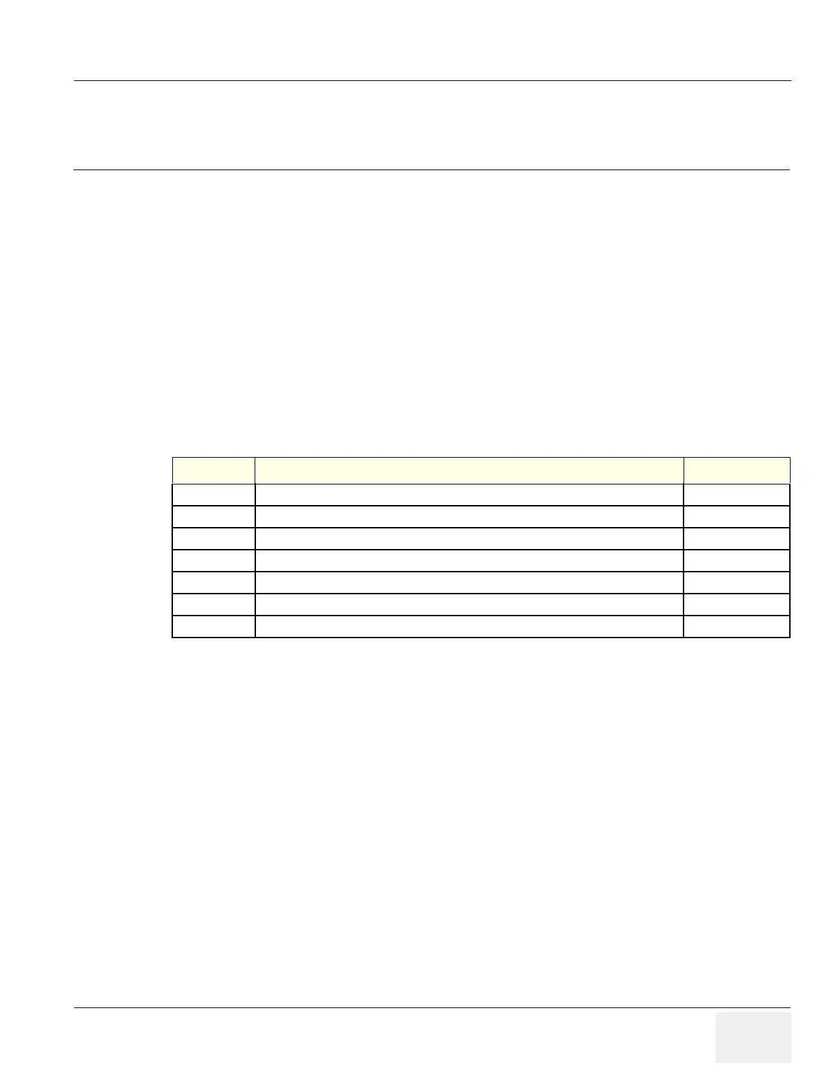
Table 7-1 Contents in Chapter 7
Section Description Page Number
7-1 Overview 7-1
7-2 Gathering Trouble Data 7-2
7-3 Screen Captures 7-4
7-4 Diagnostics 7-8
7-5 Common Diagnostics 7-9
7-6 LED Descriptions 7-20
7-7 Trouble Shooting Tree 7-22

 Loading...


