EasyManuals Logo

GE LOGIQ P5 Service Manual

GE LOGIQ P5
532 pages
To Next Page IconTo Next Page
To Previous Page IconTo Previous Page
Page #269 background imageLoading...
Page #269 background image
GE HEALTHCARE
DIRECTION 5394141, REVISION 5 LOGIQ™ P5 SEVICE MANUAL
Section 8-2 - DISASSEMBLY/RE-ASSEMBLY 8-23
8-2-6-4 Assembly procedure (cont’d)
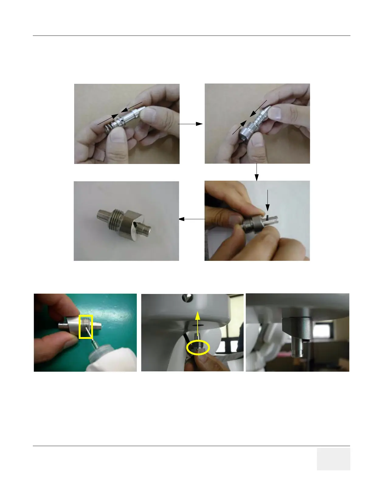
2.) Assemble the LCD locking mechanism.
a.) Put the stopper pin inside the spring and then put them inside the spring holder. Fix it with
spring pin.
b.) Put lock tite 290 on the M16 tap of the spring holder Assy and screw it.
Figure 8-36 Assembling the spring holder Assy
Figure 8-37 Screwing the spring holder Assy

Table of Contents

Other manuals for GE LOGIQ P5

Questions and Answers:

Question and Answer IconNeed help?

Do you have a question about the GE LOGIQ P5 and is the answer not in the manual?

GE LOGIQ P5 Specifications

General IconGeneral
Power Supply100-240VAC, 50/60Hz
Display15" LCD
Doppler ModesColor Doppler, Power Doppler
Imaging ModesB-Mode, M-Mode
ProbesConvex, Linear, Phased Array
ApplicationsAbdominal, Vascular, Cardiac, OB/GYN, Small Parts, Musculoskeletal
ConnectivityDICOM, USB, Ethernet
Probe Connectors3
PortabilityMobile
Operating Temperature10°C to 40°C
Relative Humidity30%

Related product manuals