EasyManuals Logo

GE LOGIQ P5 Service Manual

GE LOGIQ P5
532 pages
To Next Page IconTo Next Page
To Previous Page IconTo Previous Page
Page #271 background imageLoading...
Page #271 background image
GE HEALTHCARE
DIRECTION 5394141, REVISION 5 LOGIQ™ P5 SEVICE MANUAL
Section 8-2 - DISASSEMBLY/RE-ASSEMBLY 8-25
8-2-6-4 Assembly procedure (cont’d)
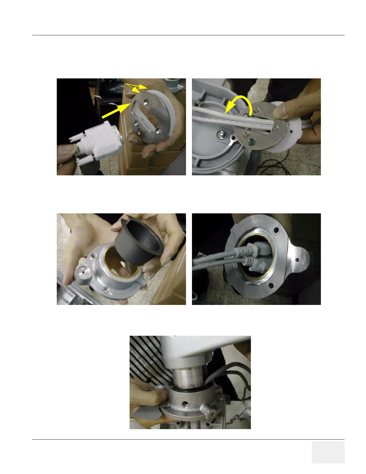
3.) Insert two of the flexible arm stoppers (A+B) to the Power Cable and DVI cable in the Order
illustrated on the figure below. Make sure that chamfered shape of the flexible Arm stopper should
face inside.
4.) Insert oilless bush into the flexible arm neck pipe and insert two cables into the flexible arm neck
pipe.
5.) Insert the flexible arm into the flexible arm neck pipe.
Figure 8-40 Inserting cables to the flexible arm stopper
Figure 8-41 Inserting the oilless bush
Figure 8-42 Inserting the flexible arm
Flexible Arm Stopper

Table of Contents

Other manuals for GE LOGIQ P5

Questions and Answers:

Question and Answer IconNeed help?

Do you have a question about the GE LOGIQ P5 and is the answer not in the manual?

GE LOGIQ P5 Specifications

General IconGeneral
Power Supply100-240VAC, 50/60Hz
Display15" LCD
Doppler ModesColor Doppler, Power Doppler
Imaging ModesB-Mode, M-Mode
ProbesConvex, Linear, Phased Array
ApplicationsAbdominal, Vascular, Cardiac, OB/GYN, Small Parts, Musculoskeletal
ConnectivityDICOM, USB, Ethernet
Probe Connectors3
PortabilityMobile
Operating Temperature10°C to 40°C
Relative Humidity30%

Related product manuals