EasyManuals Logo

GE LOGIQ P5 Service Manual

GE LOGIQ P5
532 pages
To Next Page IconTo Next Page
To Previous Page IconTo Previous Page
Page #427 background imageLoading...
Page #427 background image
GE HEALTHCARE
DIRECTION 5394141, REVISION 5 LOGIQ™ P5 SEVICE MANUAL
Section 8-7 - Mechanical Option Installation instruction 8-181
8-7-3 BT11 BW Printer Option Installation
1.) This section describes the installation procedure of the BW Printer option.
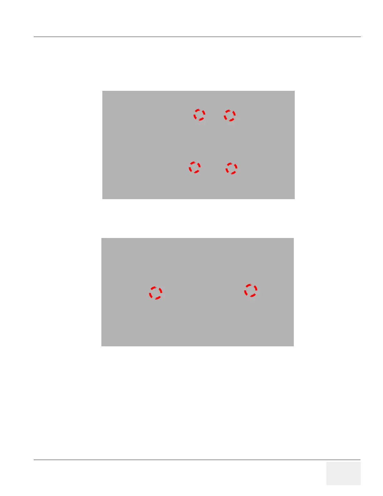
2.) Assemble the BW PRINTER to BW PRINTER FIX BRKT with screwing 4 screws (2306562, FH
M3X6).
3.) Assemble the BT11 BW PRINTER ASSY to SYSTEM using 2 SCREWS (5176744, BH M4X20).
Figure 8-250 BT11 BW PRINTER Option Installation
Figure 8-251 BT11 BW PRINTER Option Installation

Table of Contents

Other manuals for GE LOGIQ P5

Questions and Answers:

Question and Answer IconNeed help?

Do you have a question about the GE LOGIQ P5 and is the answer not in the manual?

GE LOGIQ P5 Specifications

General IconGeneral
Power Supply100-240VAC, 50/60Hz
Display15" LCD
Doppler ModesColor Doppler, Power Doppler
Imaging ModesB-Mode, M-Mode
ProbesConvex, Linear, Phased Array
ApplicationsAbdominal, Vascular, Cardiac, OB/GYN, Small Parts, Musculoskeletal
ConnectivityDICOM, USB, Ethernet
Probe Connectors3
PortabilityMobile
Operating Temperature10°C to 40°C
Relative Humidity30%

Related product manuals